Lens assembly for endoscopic lens system

a technology of endoscopic lens and lens assembly, which is applied in the field of lenses, can solve the problems of affecting the quality of endoscopic observation,

Inactive Publication Date: 2004-02-24
FUJI PHOTO OPTICAL CO LTD
View PDF7 Cites 39 Cited by
  • Summary
  • Abstract
  • Description
  • Claims
  • Application Information

AI Technical Summary

Benefits of technology

It is another object of the present invention to provide a lens assembly suitable for an endoscopic objective lens system, having spaces between adjacent lens elements hermetically sealed in such a way as to prevent intrusion of moisture over a long period of time.
It is still another object of the present invention to provide a lens assembly suitable for an endoscopic objective lens system, which can prevent condensation of water vapor on an inner surface of a first or foremost lens element of the system.
It is a further object of the present invention to provide a lens assembly suitable for an endoscopic objective lens system, having an air space between first and second lens elements of the system hermetically sealed in a reliable manner.
From the standpoint of preventing fogging, it is important to prevent condensation of water vapor on an inner surface of a first lens element which is located in a foremost position, on the side of a subject, among a plural number of lens elements which constitute an endoscopic optical lens system. Therefore, above all, an air space between a first lens in a foremost position and a second lens in a second foremost position of a lens system is hermetically sealed by the use of solder which fixedly bonds the first and second lenses together. In order to enhance the bonding strength by solder, metal film layers are formed on confronting outer peripheral surfaces, outside effective lens areas, of the first and second lenses. The metal film layers can be formed, for example, by an evaporation process. However, in order to form the metal film layers by a simpler method; it is desirable to employ a metal plating process. More specifically, the metal film layers can be formed by electroless nickel plating, followed by electroless gold plating.
In soldering lens elements together, a flux can be filled into a joint portion for the purpose of distributing solder more positively. If a flux is charged directly between metal film layers of two adjoining lens elements, it may get as far as an air space between the two lens elements. In order to avoid this, it is preferred to form a seal around the joint portion between two lens elements by applying an adhesive at the time of assembling and adjusting the optical axes of the two lens elements into alignment with each other. The use of an adhesive in this way contributes to fix the two lens elements temporarily to each other prior to soldering, and to form a seal or shield portion on the inner side of a joint portion to block intrusion of solder and flux.

Problems solved by technology

Since the first lens is fitted in an exposed state on a rigid tip end section of an endoscopic insertion instrument, its exposed outer surface is often contaminated by deposition of body fluids or other contaminants which degrade observing picture images to a considerable degree.
Fogging even in a slight degree of a center portion of the first lens element causes considerable degradations to picture images and makes the endoscopic observation difficult because light fluxes necessary for forming images are concentrated in the center portion.
A distal end portion of an endoscopic insertion instrument can be cooled off quickly due to other reasons, resulting in fogging of and condensation of moisture on the first lens element of the objective lens system.
However, considering the severe conditions in which endoscopes are used, that is, considering repeated washing, disinfection and heated sterilization of endoscopes in use, it appears almost impossible for an adhesive or seal material to prevent moisture from creeping into a lens tube of an objective lens system over a long period of time.
However, due to a difference in thermal expansion rate between metal and glass, detachment of solder or damages to lens elements may occur, for example, when the endoscopic insertion instrument is heated in an autoclave for sterilization.
For this reason, it is undesirable to solder a circumferential surface of a lens element to an inner peripheral surface of a lens tube.
This however makes it difficult to align the optical axis of the first lens element with that of the lens tube and other lens elements of the objective lens system.
Besides, air-tightness seal between the first lens and the lens tube is effective for blocking intrusion of air from front side but not effective for blocking air from back side of the first lens element or from inside of an insertion instrument.
Therefore, if moistened air exists within the insertion instrument, it can result in condensation of water vapor on the back side of the first lens element.
Normally, an endoscopic insertion instrument as a whole is not hermetically sealed in a moisture-proof state, so that it is difficult to maintain a completely moisture-free dry atmosphere within the insertion instrument.

Method used


Image

  • Lens assembly for endoscopic lens system
  • Lens assembly for endoscopic lens system
  • Lens assembly for endoscopic lens system

Examples


Embodiment Construction

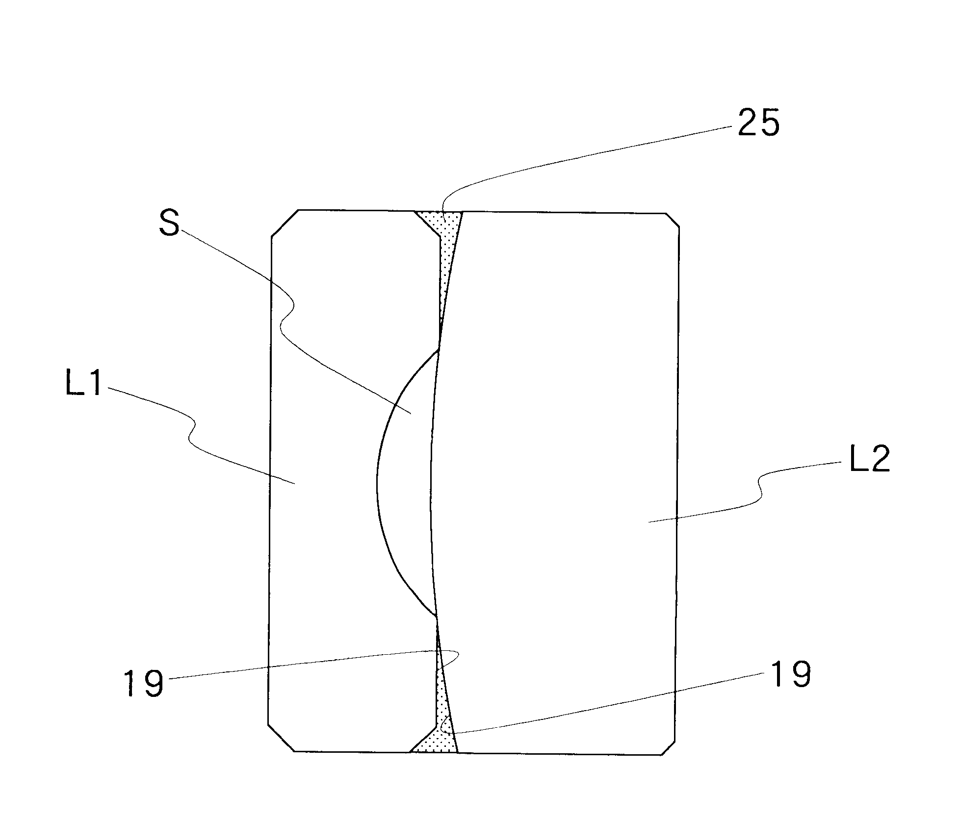
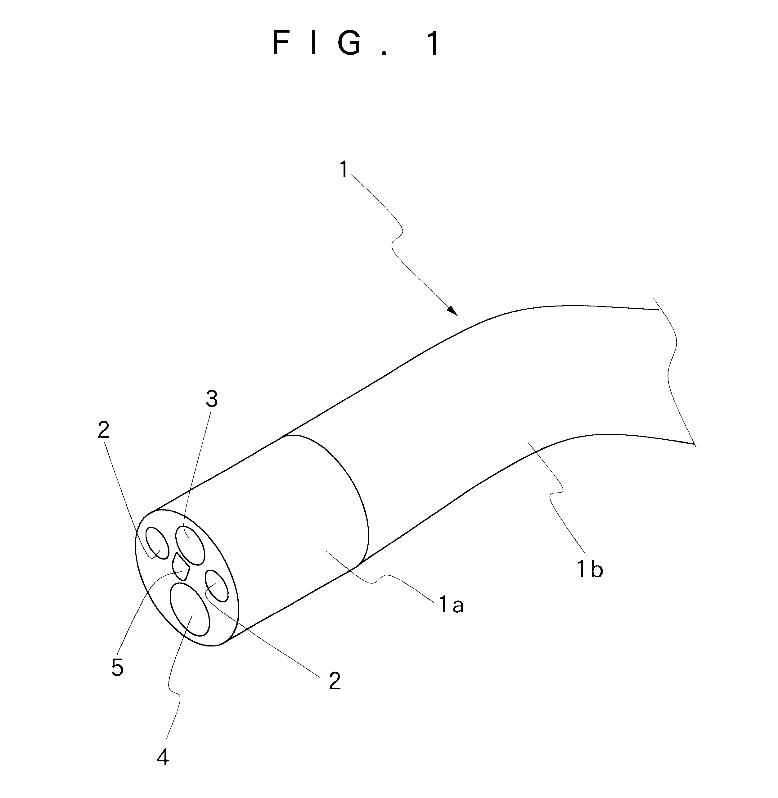
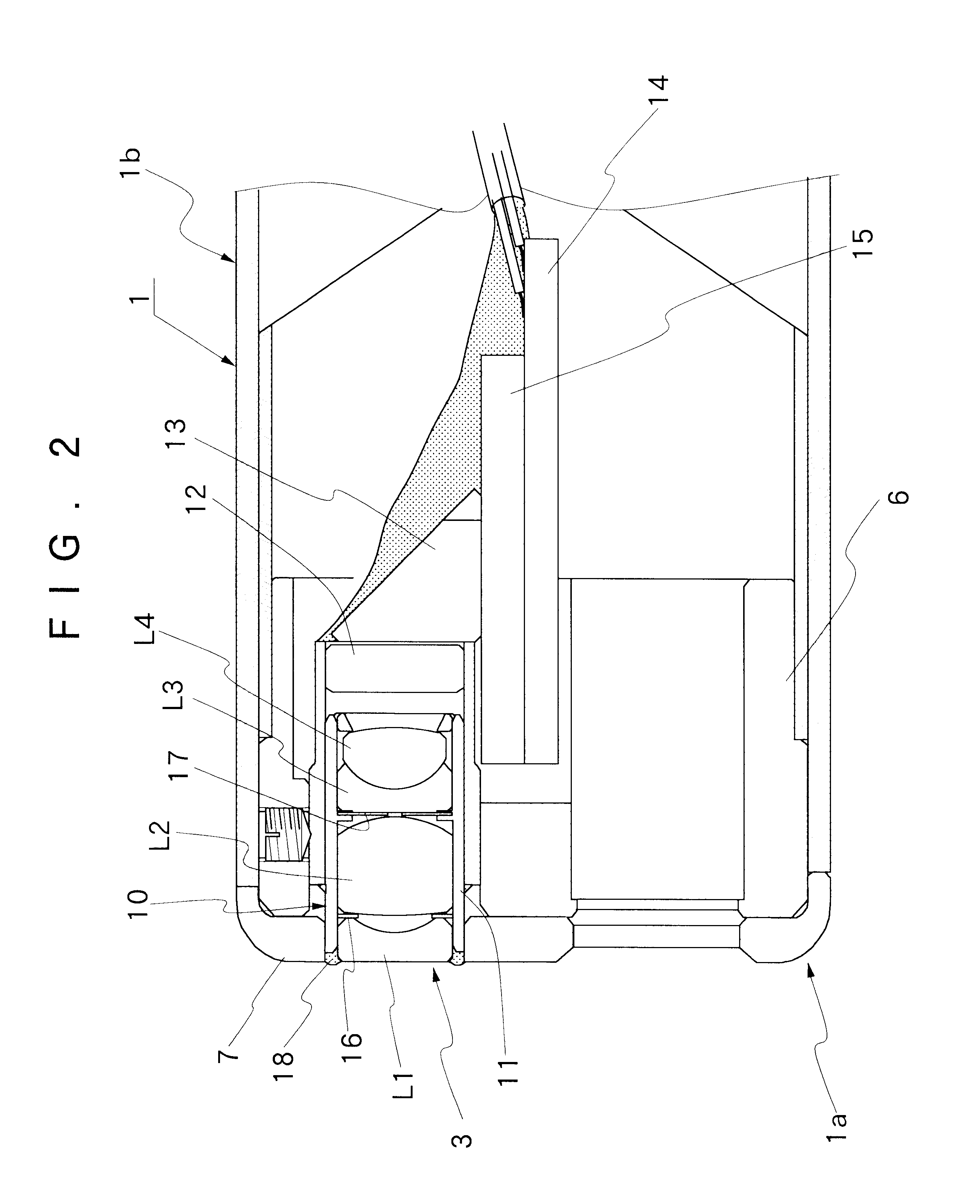
Hereafter, the present invention is described more particularly by way of its preferred embodiments with reference to the accompanying drawings. Firstly, shown schematically in FIG. 1 is a tip end portion of an endoscopic insertion instrument. In this figure, indicated at 1 is an insertion instrument to be introduced into a body cavity. At the fore distal end, the insertion instrument 1 is provided with a rigid tip end section 1ahaving a rigid structure for supporting endoscopic observation and illumination means thereon. Through an angle section 1b of a predetermined axial length, the proximal end of the rigid tip end section 1a is connected to an elongated flexible main body, which is connected to a manipulating head assembly of the endoscope although not shown in the drawings. The angle section 1b is provided for turning the rigid tip end section 1a into a desired direction. Opened in a fore end face of a casing of the rigid tip end section 1a are an illumination window 2 and an ...


PUM


Abstract

An optical lens assembly containing a plural number of lens elements for an optical system to be incorporated into a tip end portion of an endoscopic insertion instrument. Of a plural number of lenses which constitute an optical system, a metal film layer is formed on confronting outer peripheral surface portions of at least two adjacently located lenses, outside respective effective lens areas, and the two adjacently located lenses are assembled and fixedly bonded together by applying solder to the outer peripheral surface portions with a metal film layer.

Description

1. Field of the ArtThis invention relates to a lens assembly which is particularly suitable for use as an optical objective lens system on an endoscopic insertion instrument.2. Prior ArtFor insertion into a body cavity, endoscopes generally have an insertion instrument which is extended out on the front side of a manipulating head assembly. An illumination means and an endoscopic observation means are incorporated into a distal end portion of the insertion instrument for endoscopic observation and examination of intracavitary sites of interest. The illumination means includes a light guide which is constituted by a bundle of fiber optics to transmit illumination light to a distal end of the insertion instrument from a light source to which an endoscope is disconnectibly connected. A light emitting end of the light guide is disposed in an illumination window which is provided on a rigid tip end section of the insertion instrument. An illumination lens is fitted in the illumination wi...

Claims


Application Information

Patent Timeline
Patent Type & Authority Patents(United States)
IPC IPC(8): G02B23/24G02B7/02A61B1/00G02B23/26
CPCG02B7/02G02B7/025G02B23/243
Inventor WATANABE, JOJISAKAMOTO, KAZUHIROMIURA, NOBUYUKIYAMATAKA, SHUICHIKUBOYA, HIROSHIKOBAYASHI, TADASU
Owner FUJI PHOTO OPTICAL CO LTD
Why Eureka
Try Eureka