Brushless electric motor

a brushless, electric motor technology, applied in the direction of dynamo-electric components, dynamo-electric machines, piston pumps, etc., can solve problems such as heat loss and control problems, and achieve the effect of low friction loss

Inactive Publication Date: 2004-03-02
CORDIALE FR J +1
View PDF18 Cites 27 Cited by
  • Summary
  • Abstract
  • Description
  • Claims
  • Application Information

AI Technical Summary

Benefits of technology

A third object of the invention is to provide a quiet piston motor.
A fourth object of the invention is to provide a low friction loss motor.

Problems solved by technology

The problem with singular coils is reversing the current causes heat loss and control problems.

Method used


Image

  • Brushless electric motor
  • Brushless electric motor
  • Brushless electric motor

Examples


Embodiment Construction

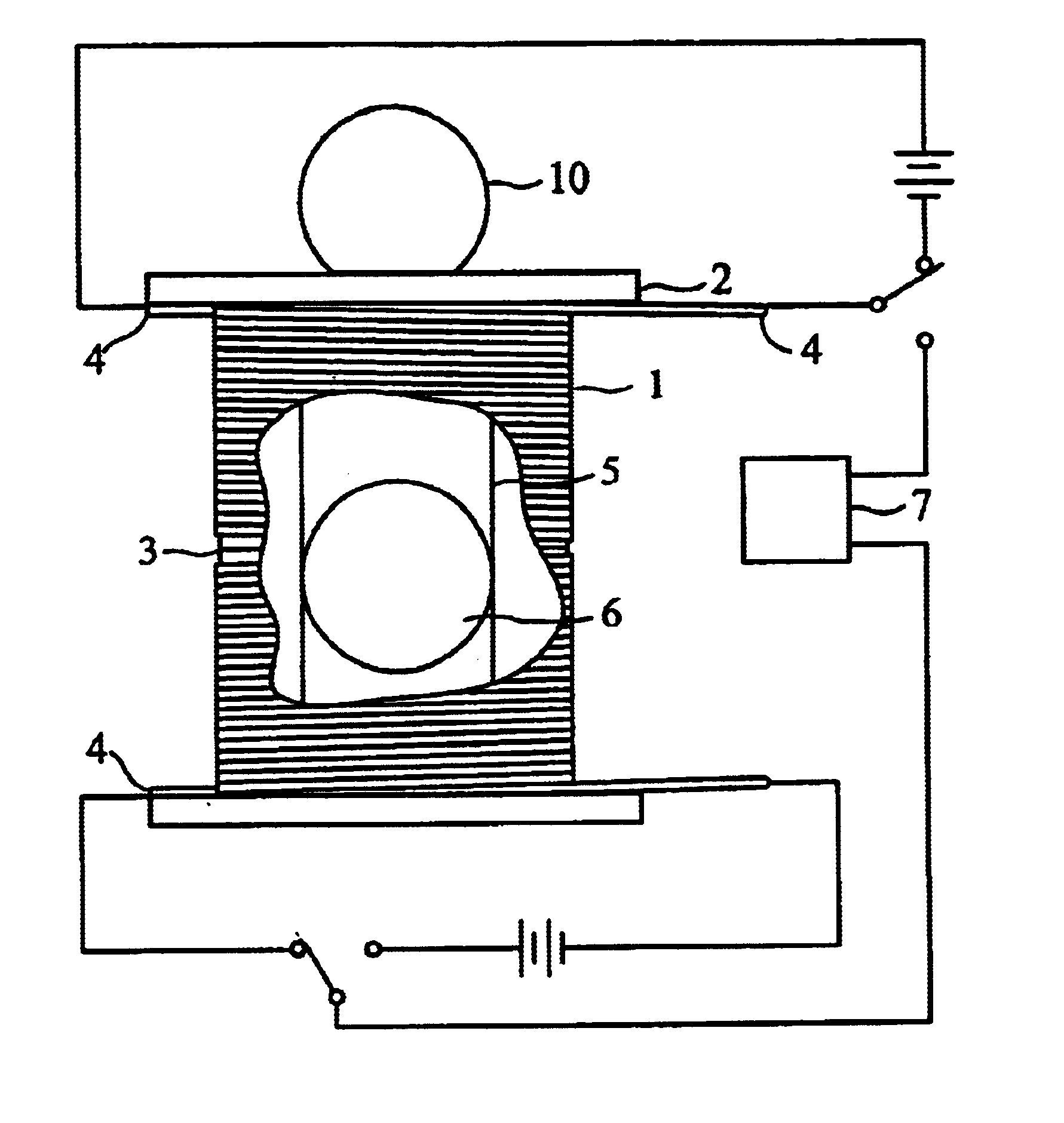
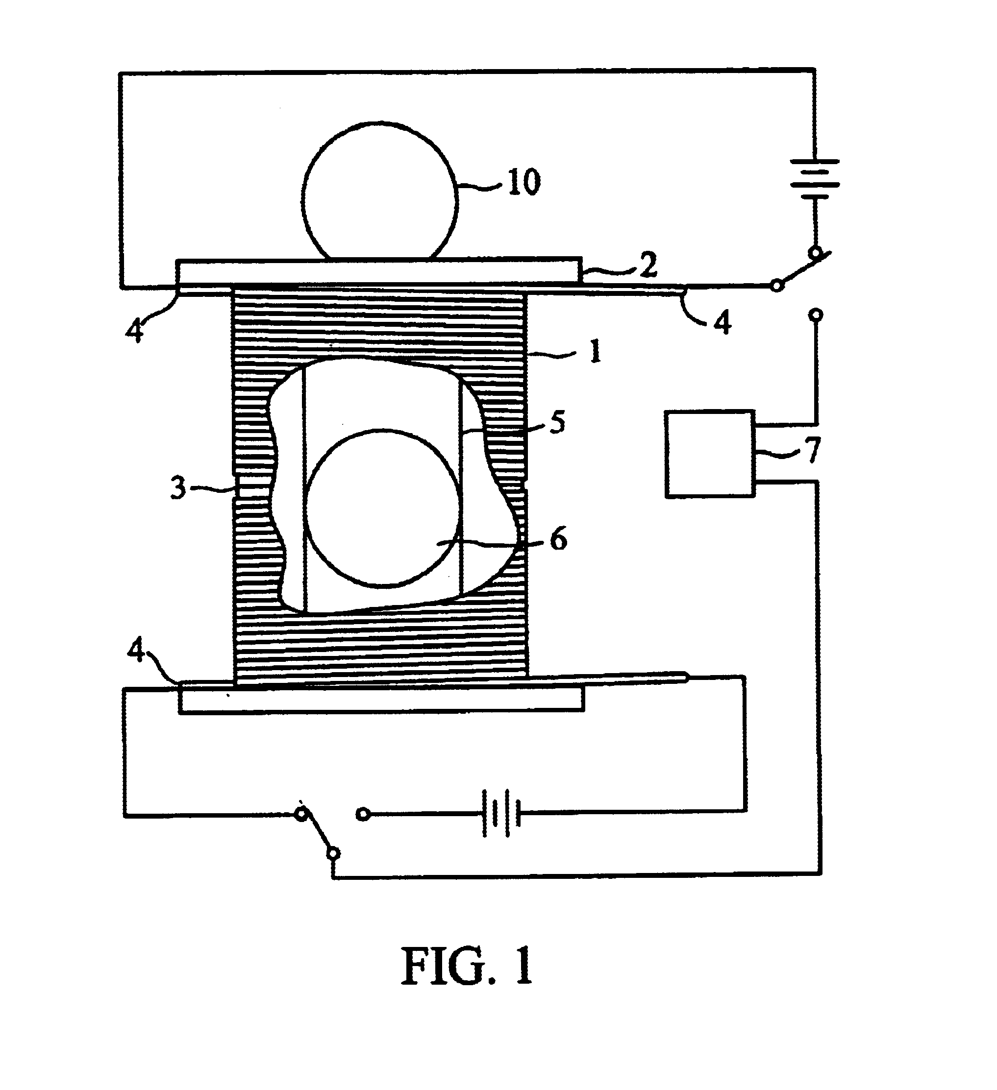
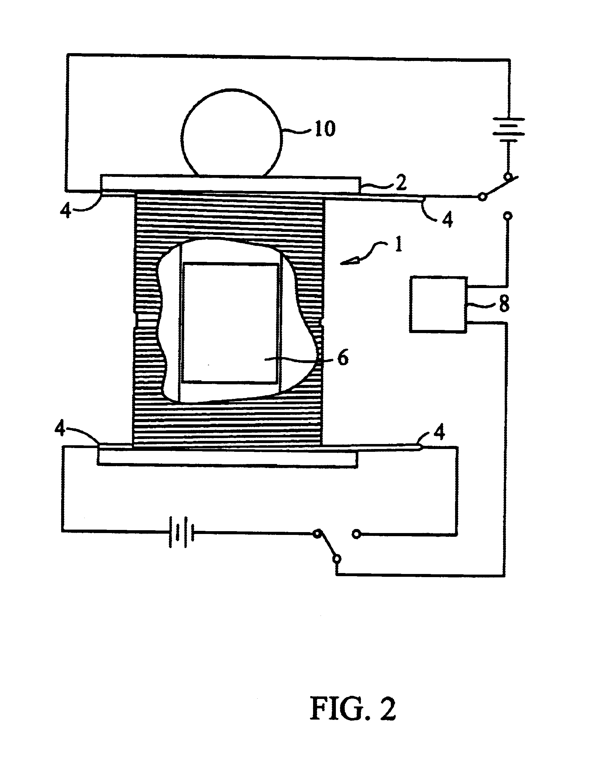
The coil 1 is shown in FIG. 1. The structure 2 is a high temperature plastic cylinder with a middle divider 3 or, alternatively, could, be two cylinders mounted together. The top and bottom are wound separately with copper wires. The result is a "split coil". Many prior art attempts have used a single coil, but they suffer from limited piston travel and must be moved to a starting position by manual or alternate means.

The coil has windings exiting at the top and bottom, as each of the two coils is entirely separate; each also has a terminus at the middle. In an alternate embodiment, both terminus for each coil are wound outwardly again so that all connections 4 are at the corresponding top or bottom of the split coil. The wound coil slides axially over a brass cylinder 5. Inside the cylinder a steel piston 6 is centrally located along the longitudinal axis. The piston can be a short cylindrical shape FIG. 2 or a spherical shape.

The coils are energized with electric current and the l...


PUM


Abstract

A prime mover using a split coil for magnetically inducing movement of a steel piston. The magnetic effects are emphasized in higher reciprocating movement by the proximate introduction of a permanent magnet. The prime mover is sparkless, brushless, quiet, low friction, and can operate on a wide array of voltages, including high frequency very low voltage signals.

Description

1. Field of InventionThis invention relates generally to the field of electro-magnetic prime movers.2. Description of the Prior ArtThe prior art includes inductors and some prime movers with singular coils. The problem with singular coils is reversing the current causes heat loss and control problems. The Inventor's approach uses a single cylinder with two separate coils which are controlled with on / off switches. Thus, the current is merely interrupted and not reversed, resulting in lower heat losses and a more efficient engine.SUMMARY & OBJECTS OF THE INVENTIONA first object of the invention is to provide an electric-powered prime mover.A second object of the invention is to provide an electric motor that will operate submersed in fluid.A third object of the invention is to provide a quiet piston motor.A fourth object of the invention is to provide a low friction loss motor.A fifth object of the invention is to provide a magnetically stimulated electric system for reciprocating a m...

Claims


Application Information

Patent Timeline
Patent Type & Authority Patents(United States)
IPC IPC(8): F04B17/03F04B17/04H02K33/00H02K33/14
CPCF04B17/046H02K33/14
Inventor CORDIALE, FRANK
Owner CORDIALE FR J
Why Eureka
Try Eureka