High temperature seal for large structural movements

a high-temperature sealing and structural technology, applied in the direction of marine propulsion, vessel construction, cosmonautic thermal protection, etc., can solve the problems of gap opening, displacement of up to several inches between adjacent elements, damage or loss of vehicles, etc., and achieve the effect of preventing leakag

Inactive Publication Date: 2004-03-09
NAT AERONAUTICS & SPACE ADMINISTATION UNITED STATES OF AMERICA THE AS REPRESENTED BY THE SEC
View PDF35 Cites 41 Cited by
  • Summary
  • Abstract
  • Description
  • Claims
  • Application Information

AI Technical Summary

Benefits of technology

The exemplary embodiment of the present invention further includes flexible sealing elements located along the outboard sides of the side walls bounding the channel. These sealing elements are implemented as pressure seals to prevent leakage between the channel and the adjacent hot structures. In the exemplary embodiment the sealing elements are axially segmented to allow them to conform to the contour of the adjacent structures and provide a generally fluid tight seal.
In some exemplary embodiments, the limited flow into the narrow passage between the edge walls of the thrust directing structures may be sufficiently low so that there is no need for a separate mechanism for cooling of the hot gases that flow into the channel. For higher temperature environments, the sealing system can be cooled using internal cooling passages or conduits that extend in the structures that form the channel. For example the passages may be comprised of one or more conduits running through the base of the channel. Coolant such as turbomachinery generated exhaust gas or hydrogen gas can be directed through the conduits to cool and protect the sealing structures from damage due to the heat of the thruster flow gases. In other exemplary embodiments, the channel may include coolant apertures which are operative to direct coolant to flow from the coolant conduits into the channel cavity. Coolant gas that has passed through the apertures mixes with the relatively higher temperature gases from the thruster flow. In this manner, the coolant gas is operative to cool the hot gases passing through the channel. This exemplary embodiment may also provide a convenient method of disposing of turbomachinery generated exhaust gas.

Problems solved by technology

Relative movements between components caused by aerodynamic and thermal loads may cause gaps to open.
If left unsealed these gaps may allow hot gas and / or unburned fuel to infiltrate into the interior of the vehicle and may cause damage to or loss of the vehicle.
In large components, aerodynamic and thermal loads can cause displacements of up to several inches between adjoining elements.
However, these seal and barrier designs are not capable of accommodating movements of several inches between adjoining elements as may occur in thrust-directing environments in some advanced aerospace engines.

Method used


Image

  • High temperature seal for large structural movements
  • High temperature seal for large structural movements
  • High temperature seal for large structural movements

Examples


Embodiment Construction

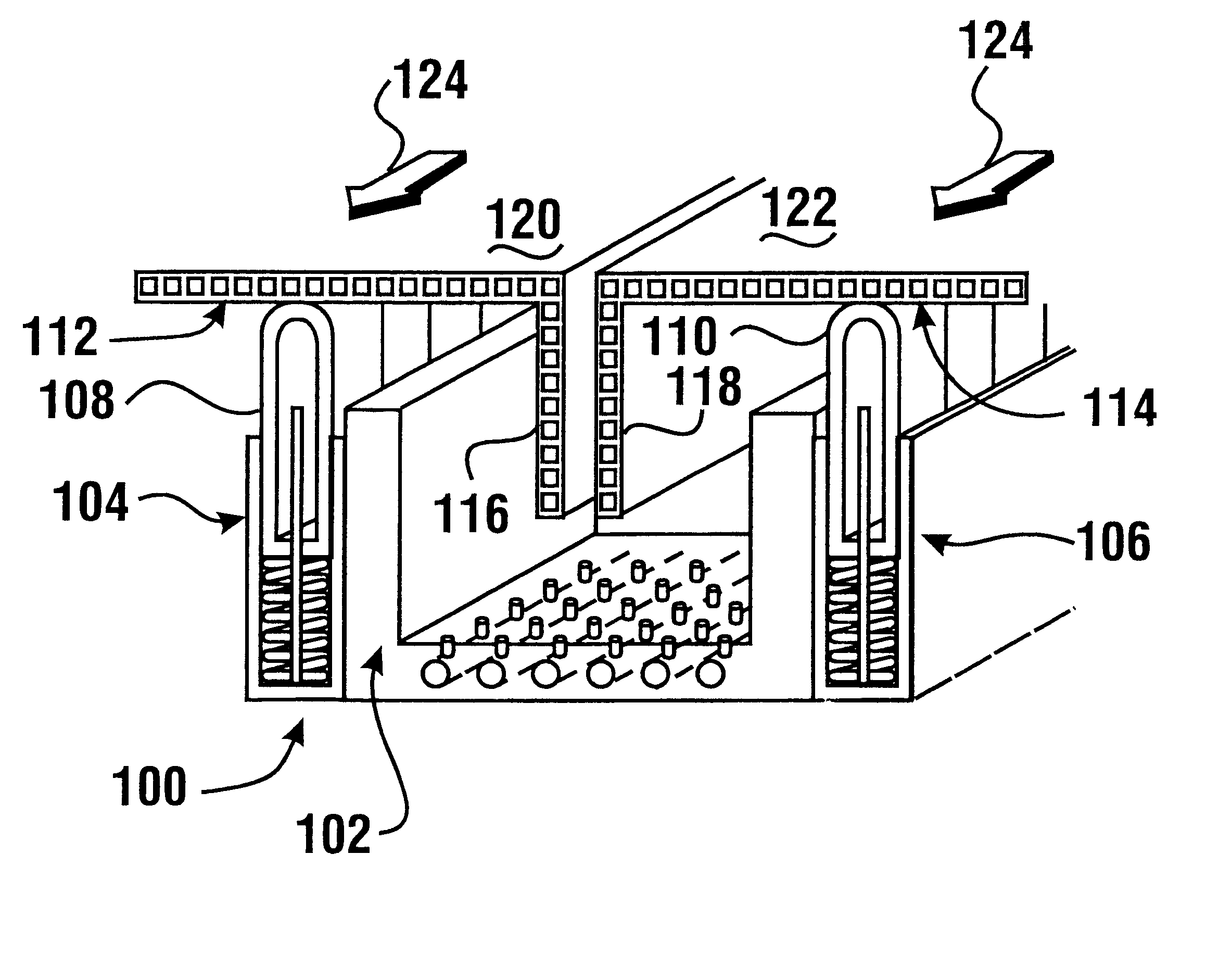
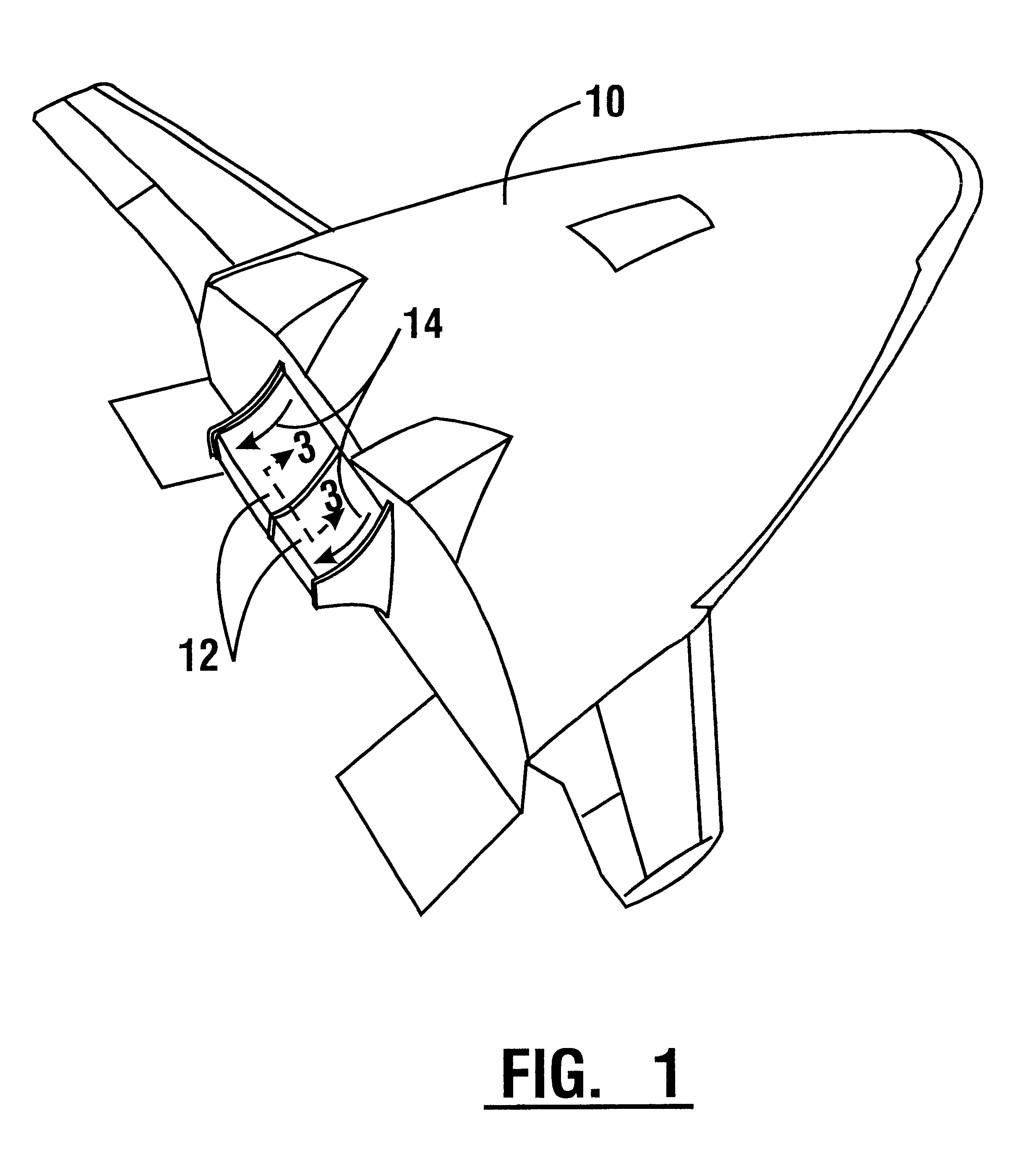
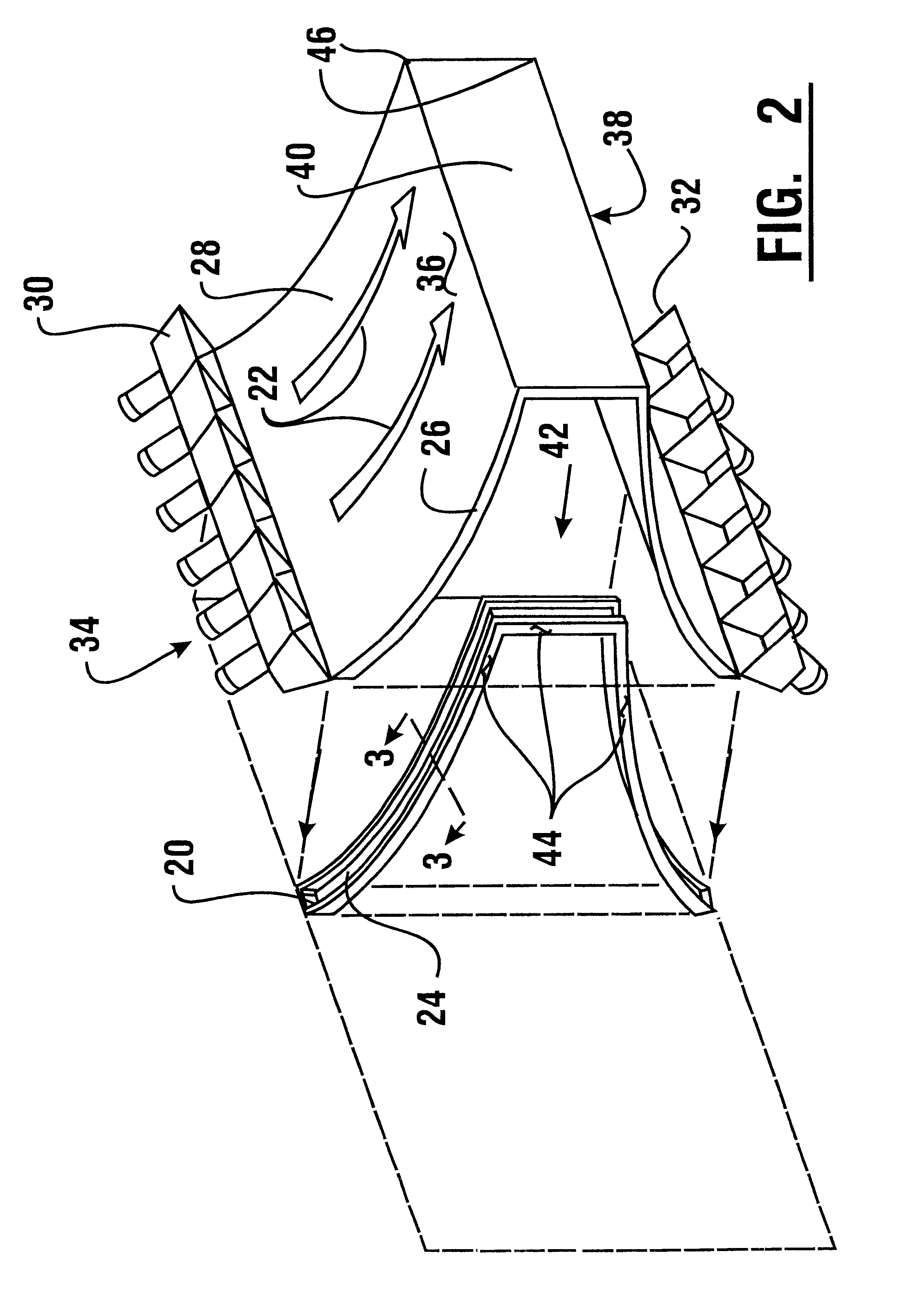
Referring now to the drawings and particularly to FIG. 1, there is shown therein a perspective view of an exemplary reusable launch vehicle 10 which includes an exemplary embodiment of a sealing system of the present invention. The vehicle 10 includes two or more rocket nozzle thrust-directing structures 12 which are alternatively referred to herein as ramps. The propulsion and maneuvering of the vehicle is achieved by controllably directing thruster flow schematically represented by arrows 14, across the ramps 12. The vehicle includes a sealing system between adjacent engine ramps to prevent hot (approximately 4,000.degree. F.) thrust gases from leaking through the gaps between adjacent ramps. The turbomachinery for supplying fuel to the rocket engines and other equipment is located behind these thrust-directing ramp structures. In addition, portions of oxygen and hydrogen fuel lines and tanks may extend into the areas within the vehicle behind these ramps. The exemplary sealing st...


PUM


Abstract

A high temperature sealing system is operative to seal an interface between adjacent hot structures and to minimize parasitic flow between such structures that move relative to one another in-plane or out-of-plane. The sealing system may be used to seal thrust-directing ramp structures of a reusable launch vehicle and includes a channel and a plurality of movable segmented sealing elements. Adjacent ramp structures include edge walls which extend within the channel. The sealing elements are positioned along the sides of the channel and are biased to engage with the inner surfaces of the ramp structures. The segmented sealing elements are movable to correspond to the contour of the thrust-directing ramp structures. The sealing system is operative to prevent high temperature thrust gases that flow along the ramp structures from infiltrating into the interior of the vehicle.

Description

This invention relates to seals that accommodate relatively large structural movements. Specifically this invention relates to a high temperature sealing system between hot structures that are required to move relative to one another in a thrust-gas-directing environment or other severe service fluid flow environment.Advanced aerospace engines and vehicles as well as other applications require sealing systems capable of blocking high temperature fluid flow. Relative movements between components caused by aerodynamic and thermal loads may cause gaps to open. If left unsealed these gaps may allow hot gas and / or unburned fuel to infiltrate into the interior of the vehicle and may cause damage to or loss of the vehicle. Relative thermal growths between components due to temperature gradients and differences in coefficients of thermal expansion between materials can also produce displacements between adjoining elements with changes in temperature. Relative movements may be both in-plane ...

Claims


Application Information

Patent Timeline
Patent Type & Authority Patents(United States)
IPC IPC(8): B64G1/22B64G1/58B64C29/00B64G1/46B64G1/50
CPCB64C29/00B64G1/58B64G1/506Y10S277/93
Inventor STEINETZ, BRUCE M.DUNLAP, JR., PATRICK H.
Owner NAT AERONAUTICS & SPACE ADMINISTATION UNITED STATES OF AMERICA THE AS REPRESENTED BY THE SEC
Why Eureka
Try Eureka