

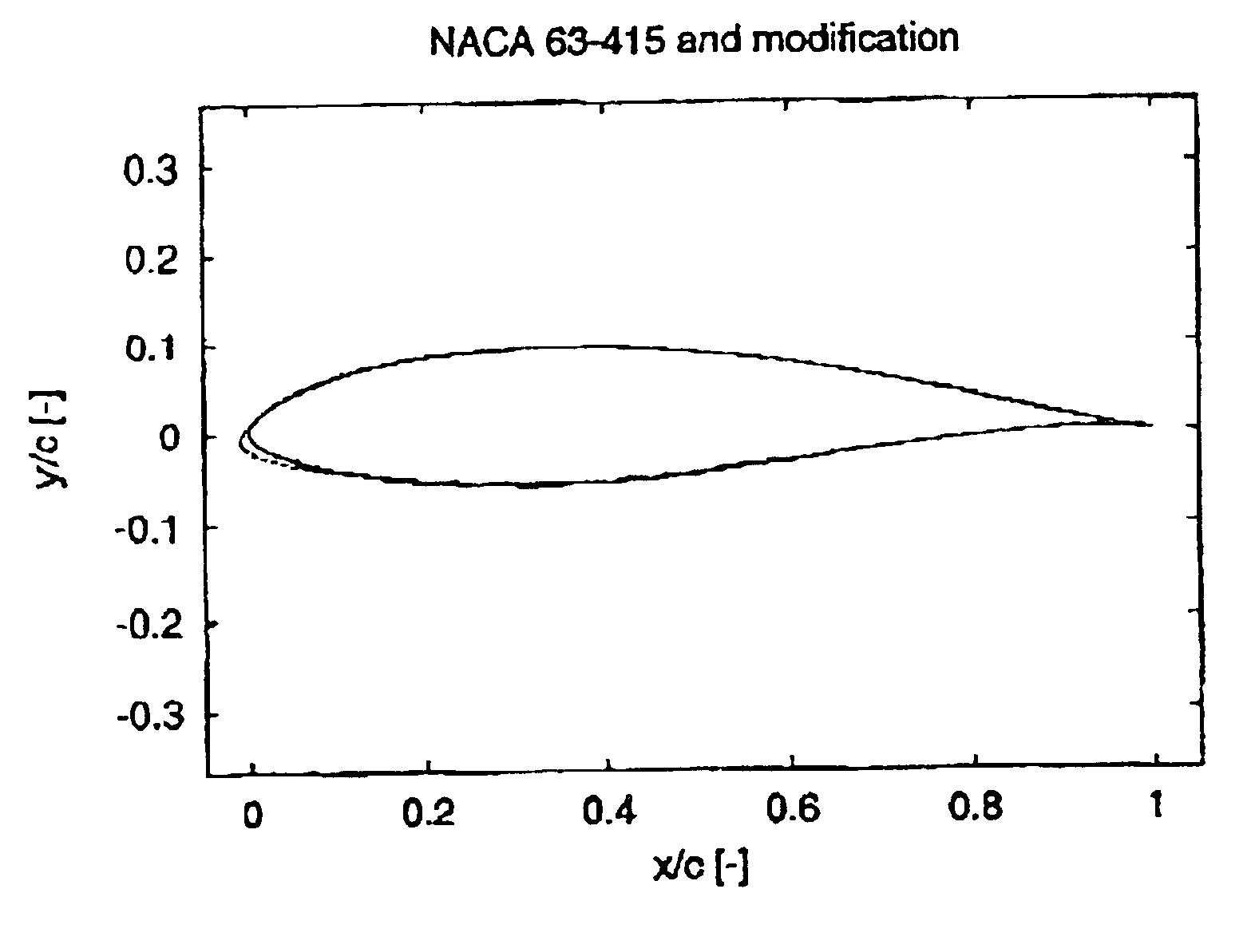
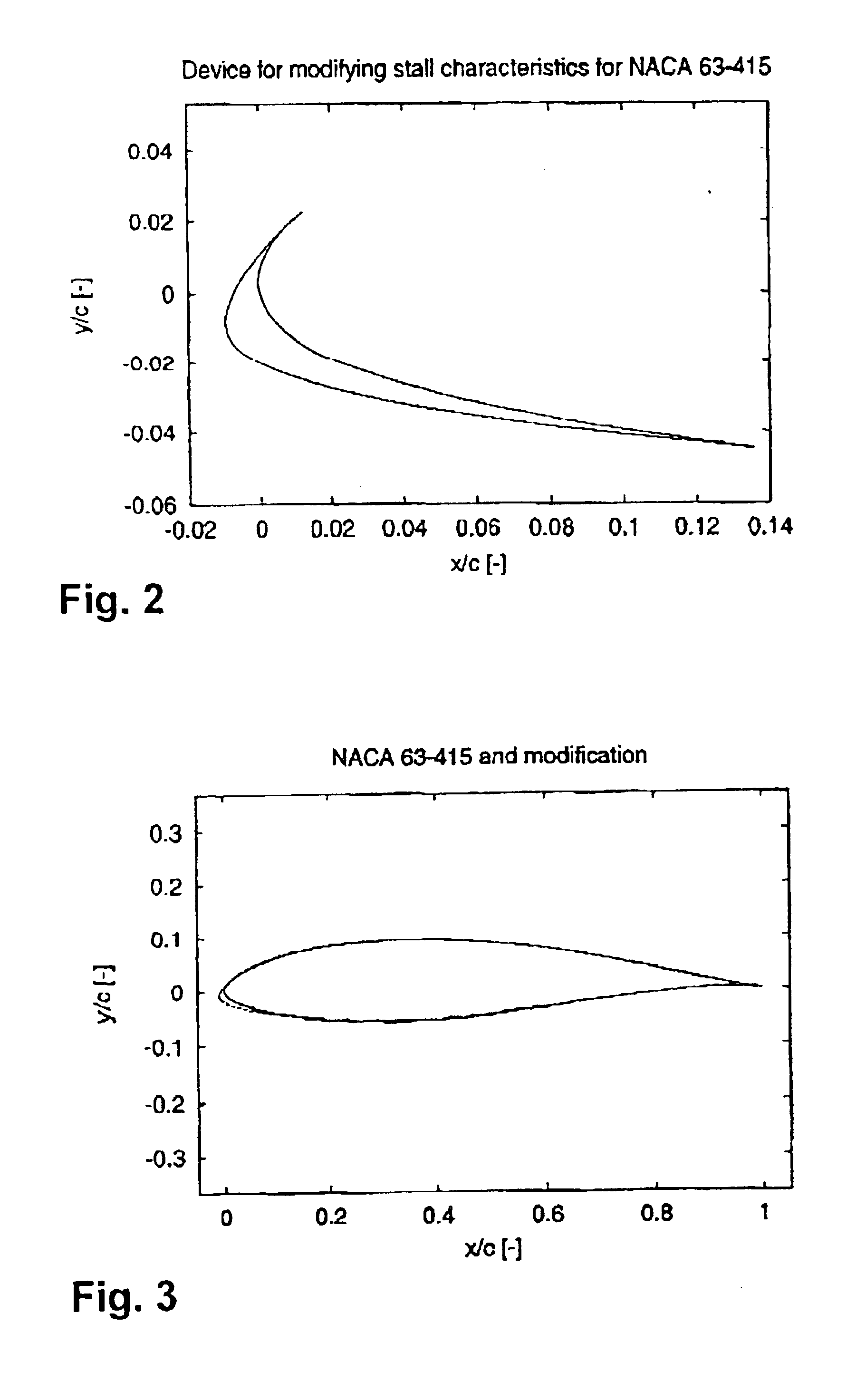
Modified wind turbine airfoil
a technology of wind turbines and airframes, applied in the direction of marine propulsion, vessel construction, other chemical processes, etc., can solve the problems of poor power quality, increased maintenance costs, and increased maintenance costs, and achieve the effect of optimizing complex problems and low lift-drag ratio
- Summary
- Abstract
- Description
- Claims
- Application Information
AI Technical Summary
Benefits of technology
Problems solved by technology
Method used
Image

Examples
Embodiment Construction
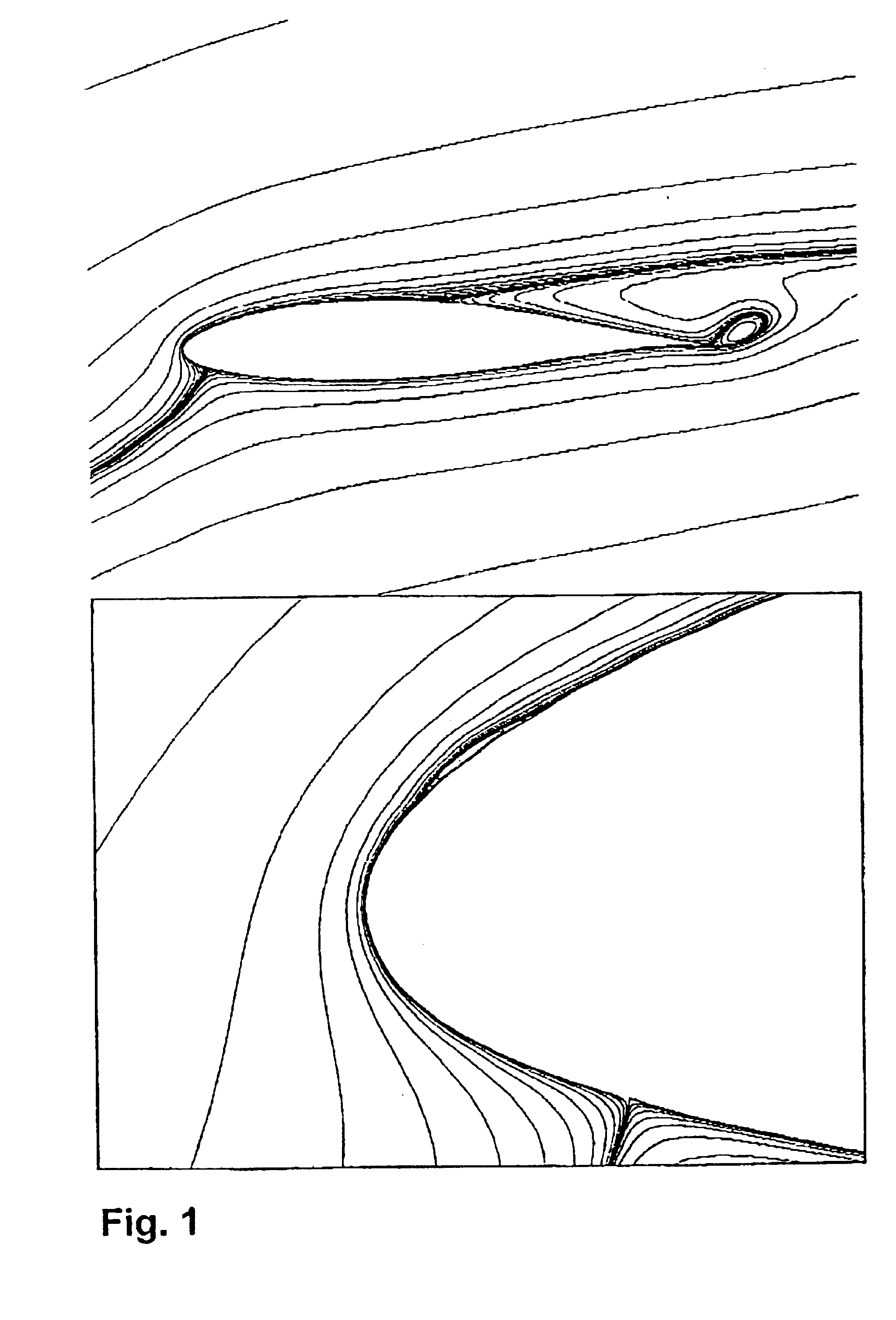
The use of mathematical and numerical means for simulating and / or calculating flow past aerodynamically shaped bodies has according to the present invention been applied in order to assure that an airfoil flow is resistant to bursting of leading edge laminar separation bubbles, resistant to leading edge roughness and / or to severe negative aerodynamic damping. Furthermore, it ensures a greater efficiency of the airfoils such greater lift-drag ratio if desired.
The design method according to the present invention contains to parts: A numerical optimisation approach and a numerical flow solver.
NUMERICAL OPTIMISATION APPROACH
The design method is based on numerical optimisation. The objective function is minimised by changing the design variables. The design variables are a number of control points that describe the airfoil shape. Inequality constraints are side values for the design variables and bounds on response parameters from flow calculations and structural calculations.
An airfoil ...
PUM
 Abstract
Description
Claims
Application Information