Liquid crystal display and method of manufacture

a technology of liquid crystal display and liquid crystal, applied in static indicating devices, instruments, non-linear optics, etc., can solve the problems of narrow viewing angle, low response speed, serious problems in shock resistance and temperature characteristics, etc., and achieve wide viewing angle, high response speed, and substantial reliability

Inactive Publication Date: 2004-03-23
JAPAN DISPLAY CENTRAL CO LTD
View PDF25 Cites 13 Cited by
  • Summary
  • Abstract
  • Description
  • Claims
  • Application Information

AI Technical Summary

Benefits of technology

A series of inventions has been made taking the present status of the technology described above into account. The prime object of the inventions is therefore to provide a liquid crystal display which has no display defects and high response speed and is therefore suitable for displaying moving pictures and which also has a wide viewing angle, since it can cause alignment transition with substantial reliability and complete it in an extremely short time. More particularly, the object of the inventions is to provide a bend alignment type liquid crystal display which has high response speed and is therefore suitable for displaying moving pictures, since it can cause bend alignment transition with substantial reliability and complete it in an extremely short time.
With the above methods, the liquid crystal molecules located at each spacer are oriented in a one-side HAN alignment in which the pretilt angle is spuriously increased by regions in at least one of the pair of substrates which differ from their corresponding regions in the other substrate. This enables an OCB type liquid crystal display in which a shift to the bend alignment can be quickly performed during an initialization process for a spray to bend transition.

Problems solved by technology

This mode, however, has drawbacks such as low response speed and narrow viewing angles.
Ferroelectric Liquid Crystals (FLC) are known as a display mode having high response speed and wide viewing angles but suffer from serious problems in shock resistance and temperature characteristics.
The Polymer Dispersed Liquid Crystal Mode, which makes use of light scattering, is a rubbingless alignment display mode, yet it still needs improvements in viewing angles and its response is not fast enough.
In reality, it is not easy to develop transition cores without fail.
In this case, the resultant panel has alignment defects and visible defects.
This case is not practical not only in view of the wait time taken for starting displaying but also in view of the power consumption of the liquid crystal display and the reliability of the driving unit.

Method used


Image

  • Liquid crystal display and method of manufacture
  • Liquid crystal display and method of manufacture
  • Liquid crystal display and method of manufacture

Examples


embodiment 1

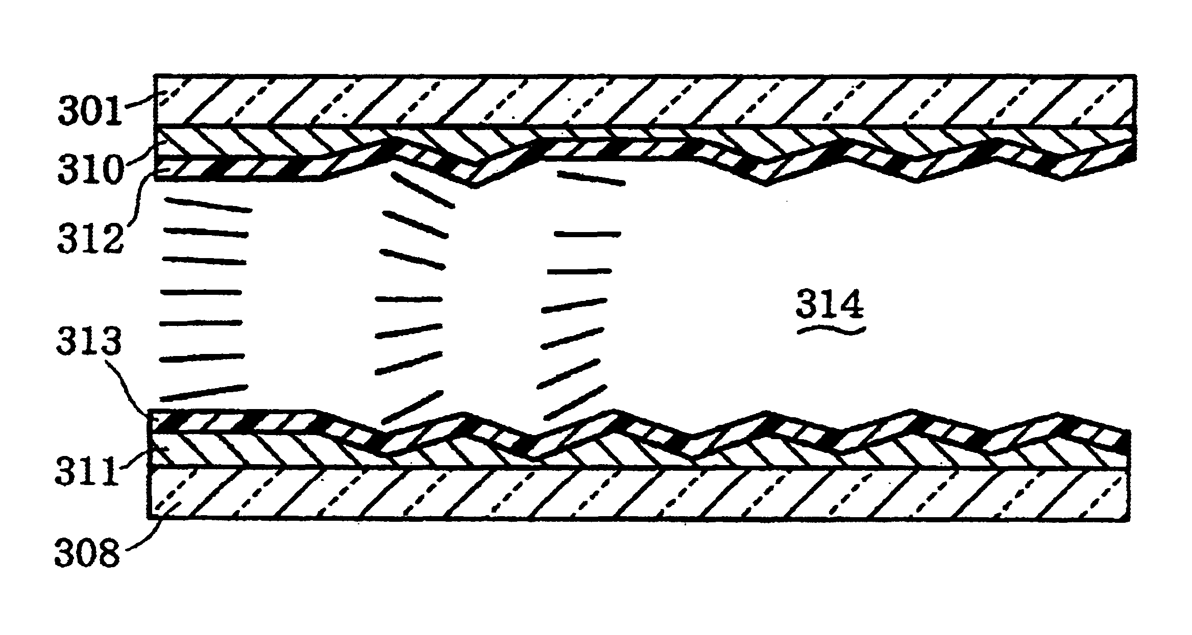
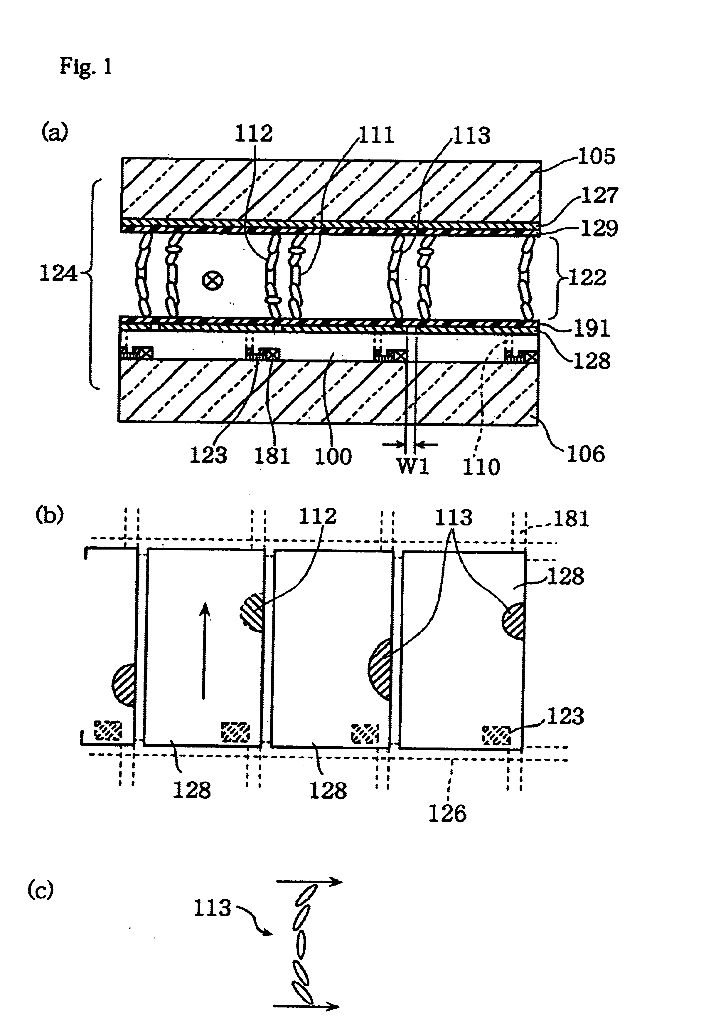
FIG. 1 shows conceptual structural views of a liquid crystal display constructed according to an embodiment 1 of the invention. Specifically, FIG. 1(a) is a conceptual structural sectional view showing the liquid crystal display on the basis of pixel unit; FIG. 1(b) is a conceptual structural plan view similarly showing the liquid crystal display on the basis of pixel unit; and FIG. 1(c) diagrammatically shows a bend alignment state and aligning direction of liquid crystal molecules as viewed from their sides.

The liquid crystal display of this embodiment has an active matrix type liquid crystal cell 124 at either or both sides of which two polarizers and a phase compensator for optical compensation (not shown) are provided.

The liquid crystal cell 124 has an opposed substrate 105 and an array substrate 106 which face each other. Arranged on the array substrate 106 are switching elements 123 made of TFT, source wiring electrodes 181 and others. The switching elements 123 and the sourc...
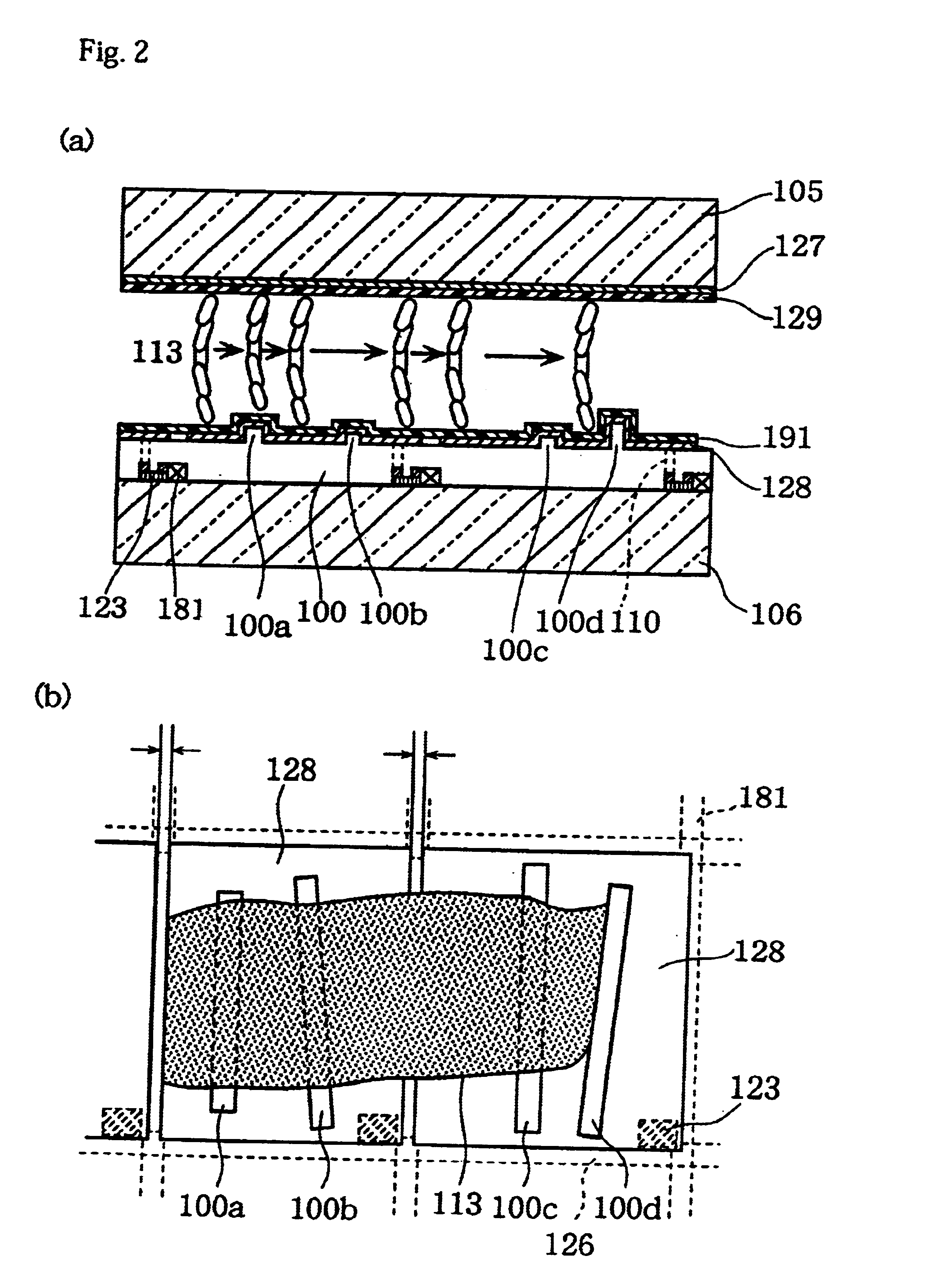
embodiment 2

FIG. 4 is conceptual structural views of a liquid crystal display constructed according to Embodiment 2 of the invention. Specifically, FIG. 4(a) is a conceptual structural sectional view showing the liquid crystal display on the basis of pixel unit, whereas FIG. 4(b) is a conceptual structural plan view similarly showing the liquid crystal display on the basis of pixel unit.

As shown in FIG. 4(a), the liquid crystal display of Embodiment 2 of the invention has an active matrix type liquid crystal cell 134 having, at either or both sides thereof, two polarizers and a phase compensator for optical compensation (not shown).

The liquid crystal cell 134 has the opposed substrate 105 and the array substrate 106 on which switching elements 133 made of TFT, the source wiring electrodes 181 and others are disposed. Laminated to the tops of the switching elements 133, the wiring electrodes 181 and others is the flattening film 100 made of a transparent insulating film material such as transpar...

embodiment 3-1

FIG. 7 shows conceptual structural views of a liquid crystal display constructed according to an embodiment 3-1 of the invention. As shown in FIG. 7(a), the liquid crystal display of this embodiment is composed of a liquid crystal cell 224 at either or both sides of which there are provided two polarizers and a phase compensator for optical compensation (not shown).

The liquid crystal cell 224 has substrates 205, 206 which face each other. Disposed on the substrate 205 is an opposed electrode 217. Disposed on the substrate 206 is pixel electrodes 271. On the electrodes 217, 271, a plurality of conductive particles 280 (at least one conductive particle is needed) are dispersedly placed, the particles being made of polymer resin particles the surfaces of which are coated with an Au thin film having a diameter of approximately 1.5 .mu.m.

Alignment layers 290, 291 are so formed as to cover the surface of the opposed electrode 217 and the surface of the pixel electrodes 271 and the conduct...


PUM

PropertyMeasurementUnit
pretilt anglesaaaaaaaaaa
diameteraaaaaaaaaa
thicknessaaaaaaaaaa

Abstract

An active matrix type liquid crystal display composed of a liquid crystal cell 124 is described. In the liquid crystal cell 124, liquid crystals at the upper and lower interfaces of a liquid crystal layer 122 inserted between an array substrate 106 having pixel electrodes 128 and an opposed substrate 105 having an opposed electrode 127 have pretilt angles opposite to each other in a positive / negative sense and are aligned in parallel with each other, forming a spray alignment. This liquid crystal display performs displaying by bend-aligning such a liquid crystal cell 124. The pixel electrodes 128 are formed on a flattening film 100 for covering switching elements 123 or wiring electrodes flat. With this arrangement, a spray to bend alignment transition can be reliably, easily caused in a short time within the liquid crystal cell pixels, so that an OCB mode liquid crystal display free from alignment defects and having high picture quality can be achieved.

Description

The present invention relates to a high response speed liquid crystal display having a wide viewing angle.One known type of liquid crystal displays which have been put to practical use is Twisted Nematic (TN) Mode liquid crystal displays using a nematic liquid crystal. This mode, however, has drawbacks such as low response speed and narrow viewing angles. Ferroelectric Liquid Crystals (FLC) are known as a display mode having high response speed and wide viewing angles but suffer from serious problems in shock resistance and temperature characteristics. The Polymer Dispersed Liquid Crystal Mode, which makes use of light scattering, is a rubbingless alignment display mode, yet it still needs improvements in viewing angles and its response is not fast enough.To overcome their drawbacks, there has been proposed the Optically Compensated Bend (OCB) Mode as a display mode having fast response and wide viewing angles (Japanese Patent Publication (KOKAI) No. 7-84254 (1995)).FIG. 21 shows a ...

Claims


Application Information

Patent Timeline
Patent Type & Authority Patents(United States)
IPC IPC(8): G02F1/1333G02F1/13G02F1/139G02F1/1337
CPCG02F1/1337G02F1/133707G02F1/1395G02F2001/133357G02F1/133357G02F1/134309G02F1/1339G02F2202/28
Inventor HATTORI, KATSUJIISHIHARA, SHOICHIUEMURA, TSUYOSHINAKAO, KENJITANAKA, YOSHINORI
Owner JAPAN DISPLAY CENTRAL CO LTD
Why Eureka
Try Eureka