Metal structural component for an aircraft, with resistance to crack propagation

a technology of metal structural components and aircraft, applied in the direction of fuselages, transportation and packaging, spars/stringers, etc., can solve the problems of cracks or rips in reinforced, i.e. strengthened, metal skin sheets, and tend to propagate along the skin sheets

Inactive Publication Date: 2004-03-30
AIRBUS OPERATIONS GMBH
View PDF17 Cites 30 Cited by
  • Summary
  • Abstract
  • Description
  • Claims
  • Application Information

AI Technical Summary

Benefits of technology

With the inventive structure of the stiffening profile member, it is especially advantageous that the post-crack residual strength of a metallic structural component having an integral construction is increased, so that such a structural component is suitable for use as a fuselage shell of an aircraft even in areas that are primarily loaded under tension and that are therefore critical in view of the fatigue characteristics of the component. Thus, it now becomes possible to use welded or otherwise integral fuselage shells for the entire fuselage of the aircraft, which advantageously reduces the effort and expense of the construction of the aircraft, due to the advantages in the fabrication. Moreover, the crack stopping or retarding measures are incorporated within the usual previously-existing cross-sectional profile shape of the stiffening profile member, and do not have a substantial effect on the stiffening member geometry (for example not requiring an external thickening or reinforcement of the previously existing stiffening members). It is thus possible to continue to use all of the previously existing manufacturing equipment and methods, without any special changes.
The inventive structure eliminates or substantially overcomes the disadvantages of the crack propagation characteristic of welded shell components, i.e. integral shell components. In the event of the occurrence of a primary crack in the fuselage skin, the simultaneously formed crack in the stiffening profile member will be stopped, deflected, or adequately hindered or retarded from further propagation in the stiffening profile member upon reaching the internally incorporated boundary surfaces between the first part and the second part of the respective stiffening profile member.

Problems solved by technology

During the subsequent operation of the aircraft, both static as well as cyclical mechanical loads arise in the fuselage, which can lead to the formation of cracks or rips in the reinforced, i.e. strengthened, metal skin sheet.
Once such a crack or rip forms in the skin sheet, it tends to propagate along the skin sheet.
On the other hand, in the case of an integral manner of construction, in which the stiffening members are integrally connected with the skin sheets, a crack propagating in the skin sheet, once it reaches a stiffening member, will also propagate into the stiffening member.
As a result of the cracking and thus weakening of the integral stiffening member, it no longer provides an effective holding-together of the skin sheet portions on opposite sides of the crack, so that the further propagation of the crack is not adequately prevented or retarded.
This cracking process leads to a reduced residual or remaining strength of the structural component after a crack has been formed therein, and to an overall disadvantageous crack propagation characteristic.
This in turn leads to an unacceptable weight increase, especially in the side and overhead shell areas of the fuselage.
However, since the thickening of the pedestal portion of the stiffening member is integral with the stiffening member, i.e. the thickening is an integral common portion (i.e. integrally joined on the atomic level) of the stiffening member, there basically still exists a danger that a crack can propagate unchecked through the entire cross-section of the thickening member.
Therefore, tools, jigs and other devices used during the fabrication of an aircraft fuselage must in many cases be altered or adapted to the changed configuration of the stiffening members, which leads to additional tooling and set-up costs.
Moreover, the crack stopping or retarding measures are incorporated within the usual previously-existing cross-sectional profile shape of the stiffening profile member, and do not have a substantial effect on the stiffening member geometry (for example not requiring an external thickening or reinforcement of the previously existing stiffening members).

Method used


Image

  • Metal structural component for an aircraft, with resistance to crack propagation
  • Metal structural component for an aircraft, with resistance to crack propagation

Examples


first embodiment

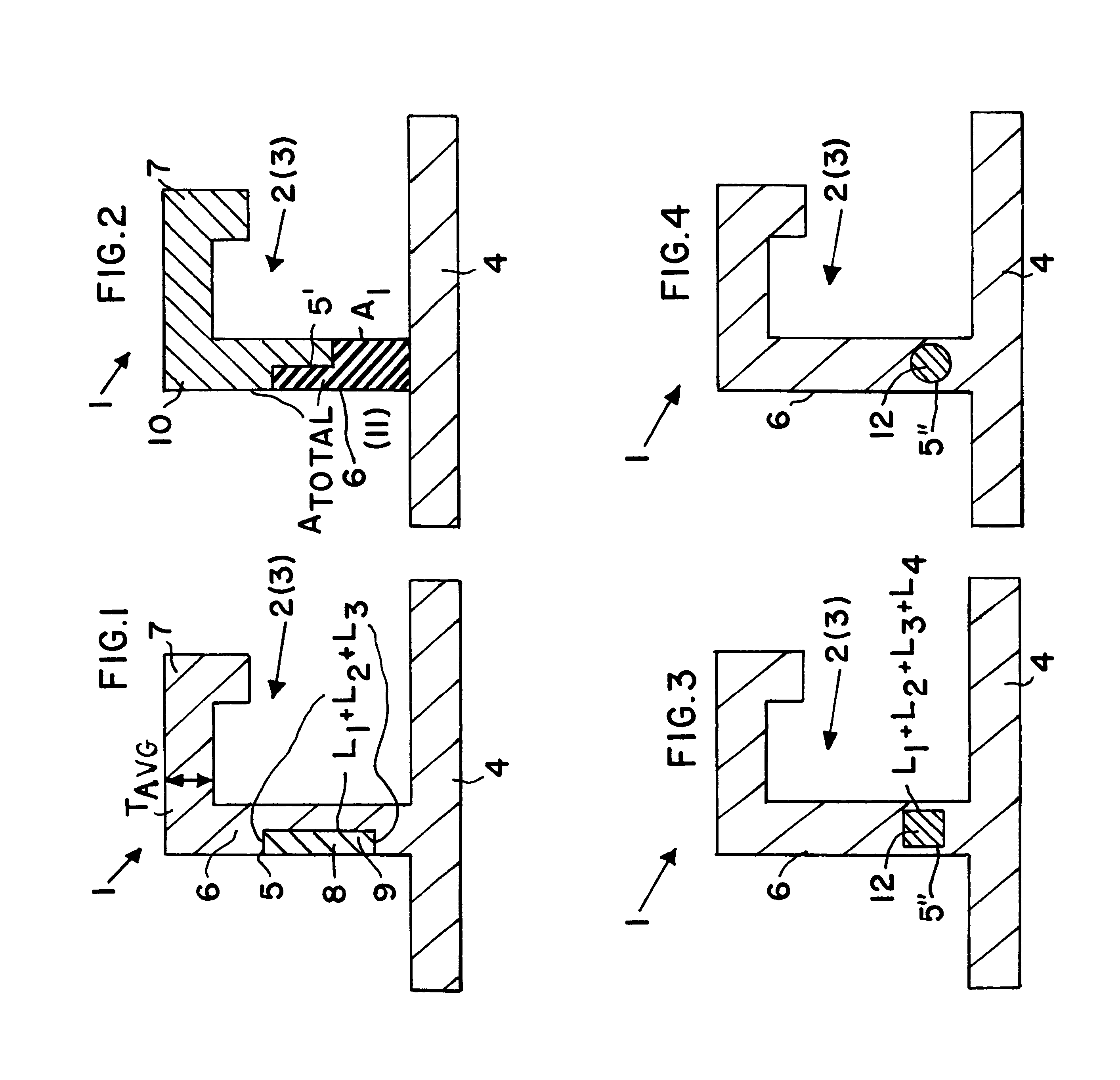
The above described boundary surface 5 is formed by providing a first part and a second part to make up the overall stiffening profile member 2, 3. In the present first embodiment of FIG. 1, the first part of the stiffening profile member 2, 3 includes a stringer web 6 and a stringer head or flange 7 that is integrally formed or connected with the stringer web 6. The stringer web 6 is integrally connected with the skin sheet 4 along a base or pedestal edge of the stringer web 6. The second part comprises a partial component 8, here embodied as a narrow rectangular sectional profile member, e.g. having an .vertline.-profile. This partial component or .vertline.-profile member 8 is let into a correspondingly shaped recess 9 in the side of the stringer web 6. Various joining methods can be used for joining the partial component or .vertline.-profile member 8 into the stringer web 6, for example by means of adhesive bonding, soldering, press-fitting, or the like.

In any event, with such ...

second embodiment

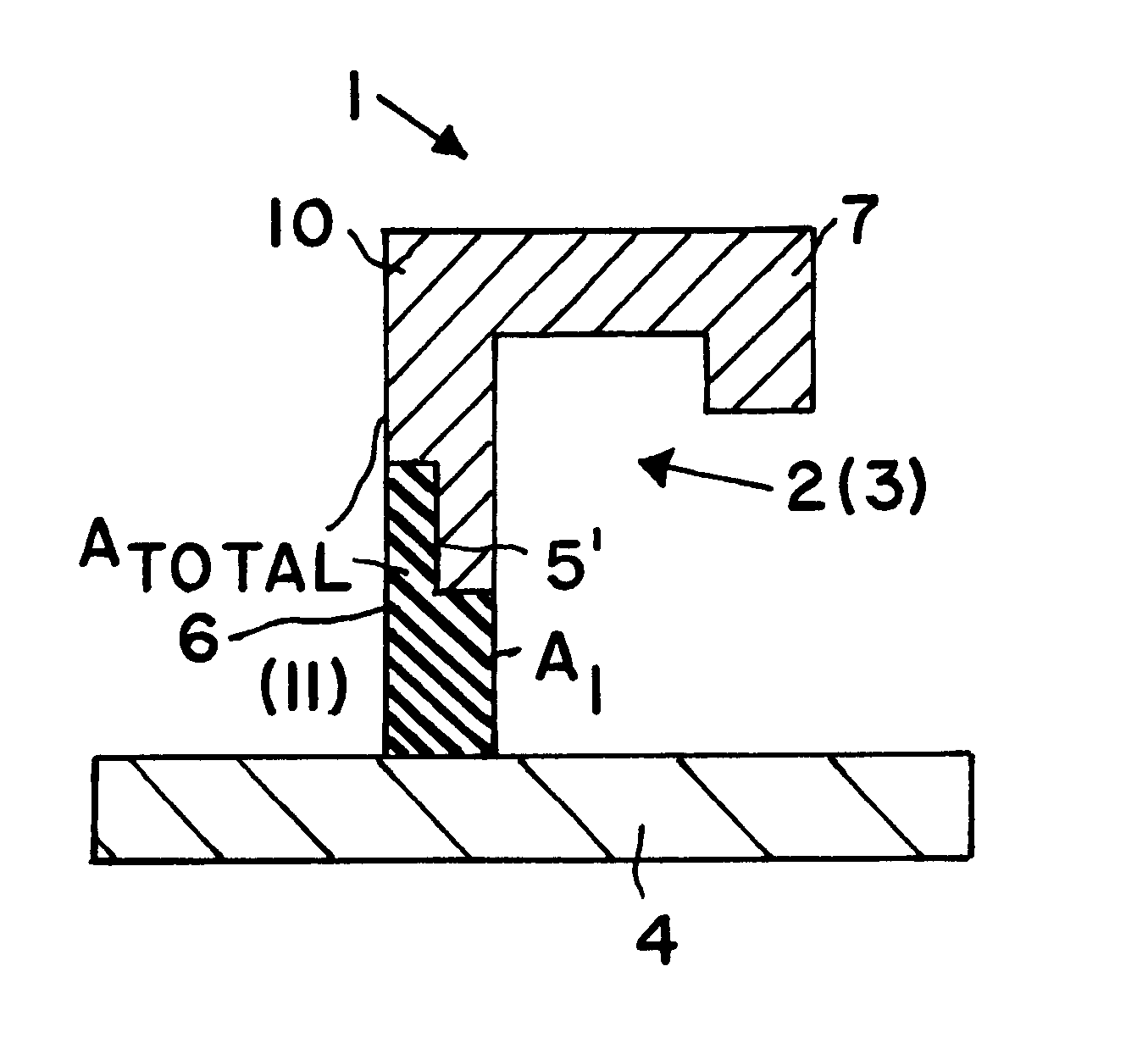
FIG. 2 shows a cross-section through an inventive structural component 1 in the area of a stringer 3 integrally arranged and connected on a skin sheet 4. An internal boundary surface 5' has been incorporated into the stiffening profile member 2, 3 of this integral structural component 1, in that the stiffening profile member 2, 3 is made up of a first part comprising a web base or pedestal 11 that is integrally connected with the skin sheet 4, as well as a second part comprising a separate partial component 10 that includes a second portion of the stringer web 6 and a stringer head or flange 7 provided thereon. The stringer web pedestal 11 forms a first portion of the stringer web 6. The two separate parts, i.e. the partial component 10 and the stringer web pedestal 11, are connected to each other in a non-integral manner, using any conventionally known differential joining technique, such as adhesive bonding, soldering, compression-joining, etc., whereby the internal boundary surfa...

third embodiment

FIG. 3 shows a cross-section through a further third embodiment of an inventive structural component 1 in the area of a stiffening profile member or stringer 2, 3 integrally connected with a skin sheet 4. An internal boundary surface 5" is formed within 20 the integral structural component 1, by incorporating a second separate component 12 within a stringer web 6 of the overall stiffening profile member 2. In this embodiment, the geometric form of this component 12 is preferably rectangular or quadratic, and particularly square as shown in FIG. 3. However, it is possible to alternatively provide such a second component 12 with a different cross-sectional shape, such as a round circular cross-sectional shape as shown in FIG. 4, or a polygon shape.

Just as described in connection with the first embodiment above, it also pertains here that the sum of all of the boundary surface lengths L.sub.1, L.sub.2, L.sub.3 and L.sub.4 is preferably greater than or equal to the average thickness of ...


PUM


Abstract

A metallic structural component for an aircraft includes stiffening profile members integrally formed or connected onto a skin sheet. Each stiffening profile member includes a first part integrally connected to the skin sheet, and a second part non-integrally connected to the first part so as to form an internal boundary surface within the multi-part stiffening profile member. If a crack forms in the skin sheet and propagates into the first part of the stiffening profile member, the internal boundary surface resists the further propagation of the crack past this boundary surface. The crack propagation resistance is improved, the remaining strength of the structural component after formation of a crack is increased, and the overall structural component is light in weight. The outer contour of the stiffening profile member is not affected by the provision of the separate first and second parts or the internal boundary surface therebetween.

Description

PRIORITY CLAIMThis application is based on and claims the priority under 35 U.S.C. .sctn.119 of German Patent Application 101 63 848.5, filed on Dec. 22, 2001, the entire disclosure of which is incorporated herein by reference.The invention relates to a metal structural component for an aircraft, including a plurality of stiffening profile members arranged on and integrally connected with a metal skin sheet.BACKGROUND INFORMATIONThe majority of aircraft structures, such as the fuselage and the wings for example, are fabricated of metal or metallic materials. In order to satisfy primarily the stiffness and strength requirements, the prevailing conventional construction technique for fabricating such aircraft structures is to provide stiffening members on a metal skin sheet. An especially meaningful example thereof is the fuselage, of which the outer fuselage skin is reinforced or strengthened by stringers extending in the longitudinal direction and by frames extending in the circumfe...

Claims


Application Information

Patent Timeline
Patent Type & Authority Patents(United States)
IPC IPC(8): B64C1/12B64C1/00B64C3/00B64C3/18
CPCB64C1/12B64C3/182
Inventor SCHMIDT, HANS-JUERGENASSLER, HERWIG
Owner AIRBUS OPERATIONS GMBH
Why Eureka
Try Eureka