Riser support for floating offshore structure

a technology for offshore structures and risers, which is applied in vessel construction, special purpose vessels, and borehole/well accessories, etc., can solve the problems of not being designed for drilling or extensive workover operations, the arrangement of riser supports does not permit individual riser length fluctuations commonly occurring, and the risers of this configuration are subject to cyclical bending

Inactive Publication Date: 2004-03-30
SOFEC
View PDF20 Cites 44 Cited by
  • Summary
  • Abstract
  • Description
  • Claims
  • Application Information

AI Technical Summary

Benefits of technology

Another object of the invention is to provide a floating framework and a platform hull arrangement that provides individual riser buoyancy, a draw works decoupled from hull motion of the platform, and decoupling of hull motion from the risers so as to eliminate cyclical bending of the risers.
A floating offshore arrangement substantially decouples pitch, roll and heave motions between an outer hull structure and buoyantly supported risers which are vertically oriented by a frame or support buoy positioned within the interior of the hull structure. The risers are arranged and designed to slide vertically with respect to the support buoy. The support buoy is coupled to the outer hull structure by a mechanism that allows it to remain in a nearly vertical orientation at a fixed distance above the sea floor while the outer hull is free to heave, roll and pitch. The support buoy is allowed to rotate in a pendular fashion in response to the angularity of risers produced by outer hull excursions in surge and sway.

Problems solved by technology

As a result, the risers of this configuration are subjected to cyclical bending.
Furthermore, as the adjustable riser supports do not provide any capability of axial vertical flexure relative to one another, this arrangement of riser support does not permit individual riser length fluctuations commonly occurring as a result of operating riser temperature and internal pressure changes.
The vessel does not have a moonpool and is not designed for drilling or extensive workover operations.
A significant disadvantage of the U.S. Pat. No. 4,966,495 arrangement is that the semi-submersible "outer" vessel has a large waterplane area thereby producing large forces in tension due to wave action and hull extension.
Another disadvantage is that the drilling or workover equipment is mounted on the outer vessel which induces bending in the drill pipe when there is relative pitch between the outer body and the inner riser support buoy.
Another disadvantage of the arrangement of U.S. Pat. No. 4,966,495 is that individual riser elongation due to temperature and / or internal pressure variation is not allowed for.
Furthermore any pitch of the inner riser support buoy results in fluctuation in riser tension because of the large waterplane area of the inner support buoy.
The riser support module, being installed within a semi-submersible is exposed to the environment and suffers loading induced thereby.
Hanging the risers from the top of the buoy results in static instability, because as the buoy is pulled into the buoyant hull, it becomes unstable and tends to invert unless the buoy is ballasted to negative buoyancy.
The riser frame is not tethered to the sea floor, does not have buoyancy, and is rigidly connected to the semi-submersible hull during operation, so the riser frame induces wear through its contact with the risers and their main buoyancy members due to semi-submersible heave.

Method used


Image

  • Riser support for floating offshore structure
  • Riser support for floating offshore structure
  • Riser support for floating offshore structure

Examples


Embodiment Construction

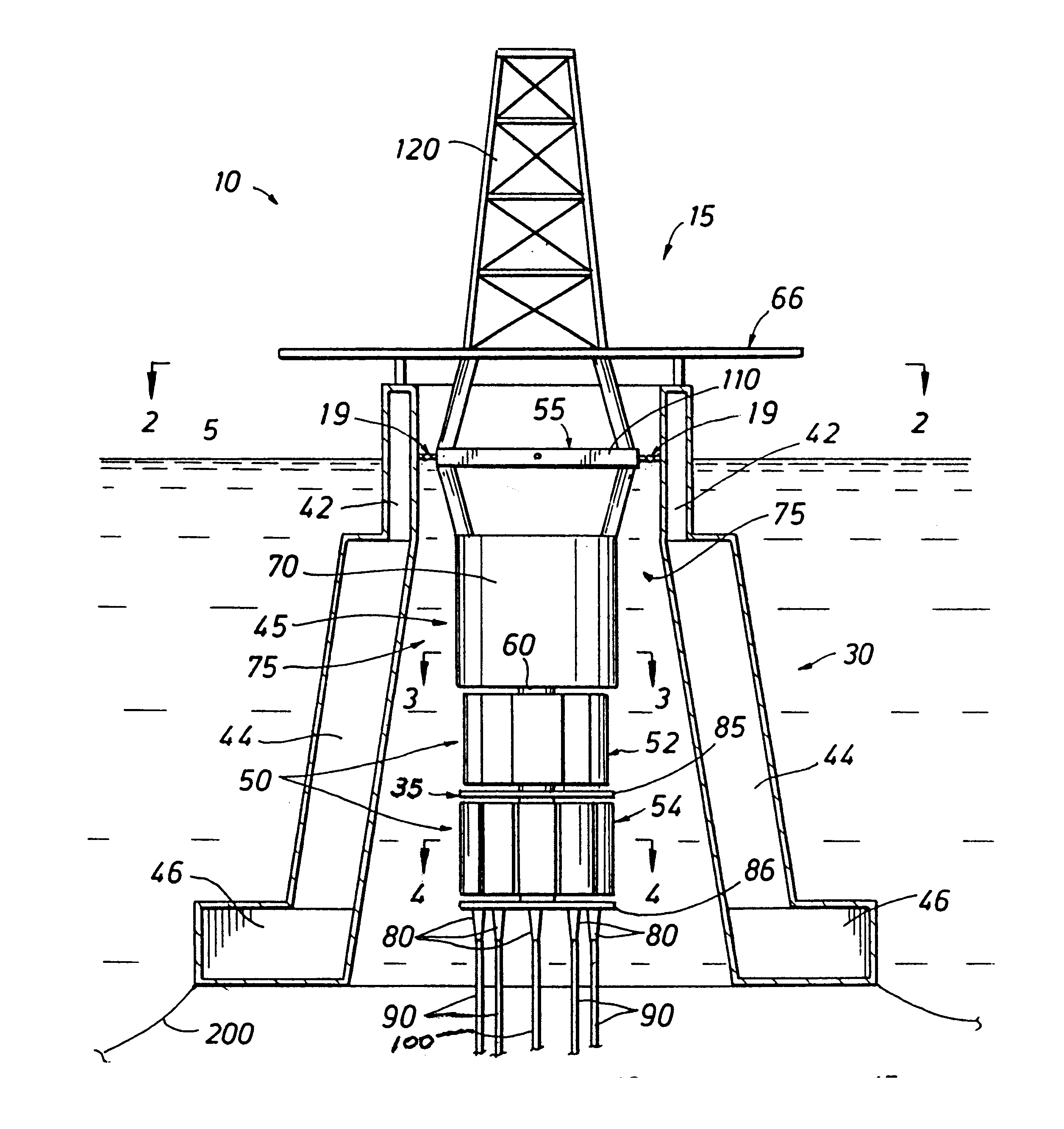
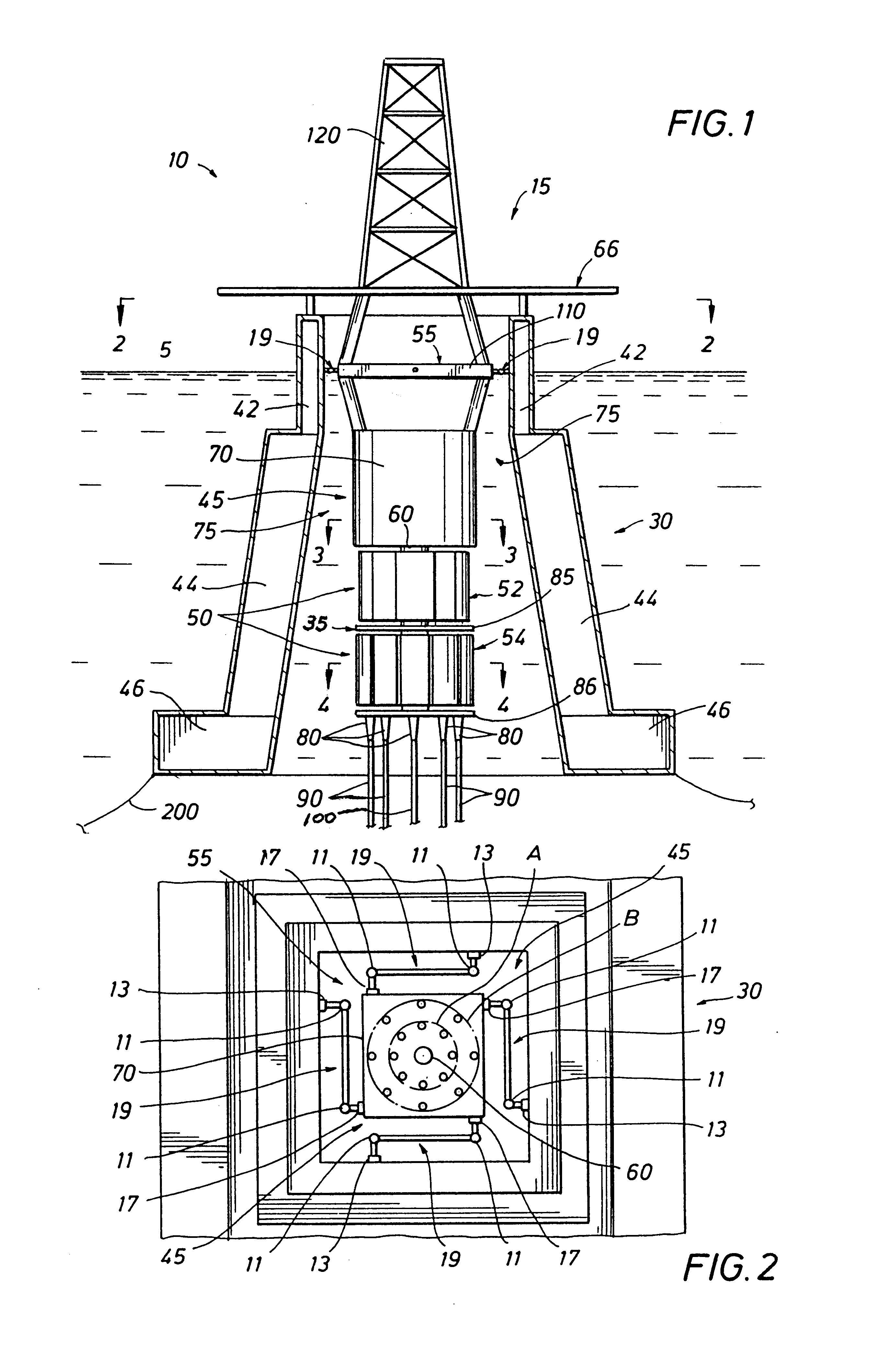
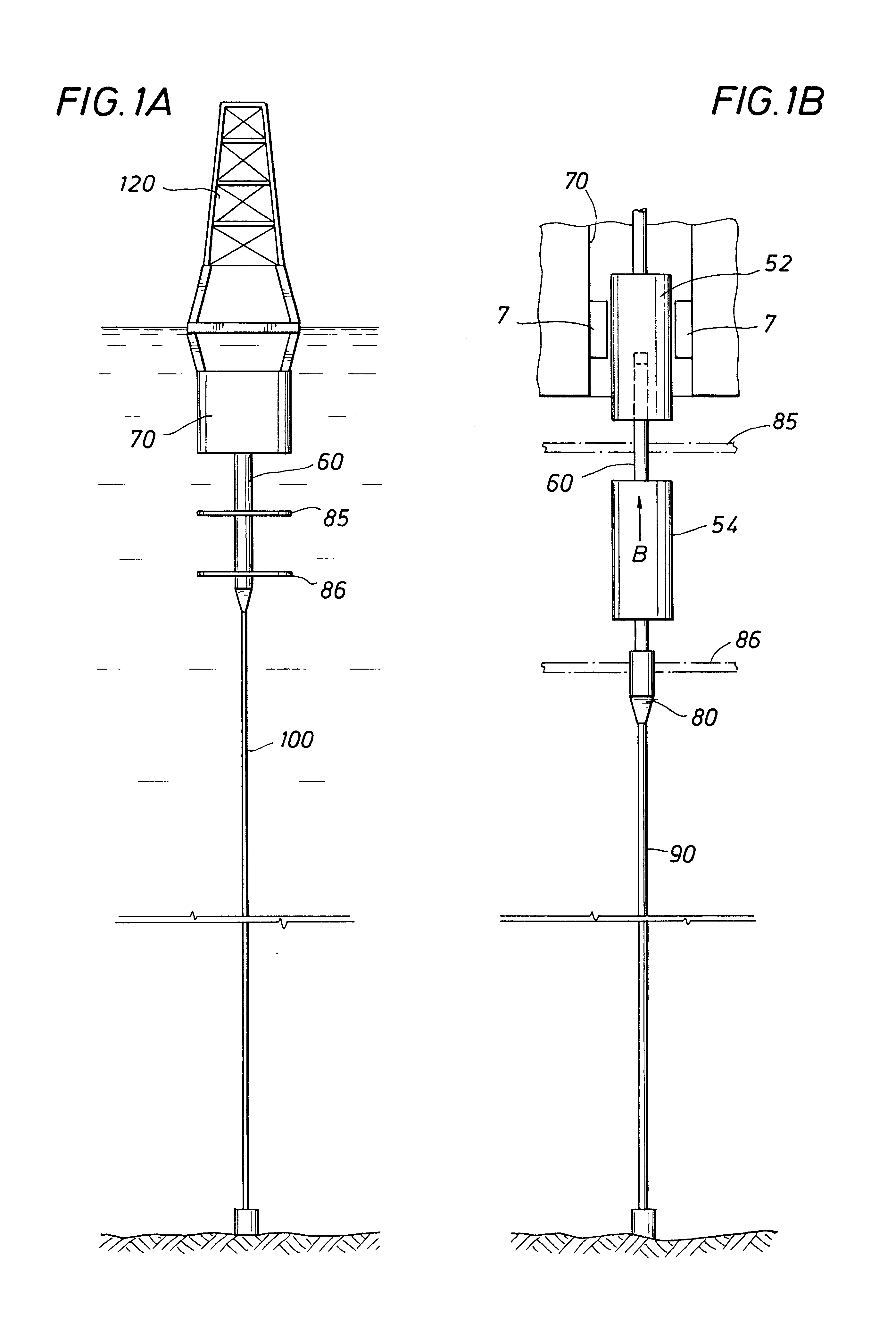
FIG. 1 illustrates the invention in an embodiment of a floating offshore platform 10. In this embodiment, the floating offshore platform 10 includes an inner structure 15 and an outer hull structure 30. The inner structure 15 includes a riser guide structure 35 and a support buoy structure 45 with a drilling draw works 120 mounted thereon.

The riser guide structure 35 is fixed with respect to the sea floor by means of at least one riser or tension member. A support buoy structure 45 is fixedly coupled to the riser guide structure 35. The outer hull structure 30 is coupled to the support buoy structure 45 by a connection mechanism 55. The heave, pitch and roll motions acting on the outer hull structure 30 are decoupled from inner structure 15 (riser guide structure 35 and support buoy structure 45) by means of the connection mechanism 55. Transfer of the heave forces on the buoy structure 45 to the riser guide structure 35 is reduced, if not completely eliminated, by means of the teth...


PUM


Abstract

A floating offshore platform configuration is provided, which decouples pitch, roll, and heave motions from acting on tensioned risers and accommodates the angular displacement induced by floating offshore platform surge and / or sway excursion without inducing bending in the riser at its entrance to the floating offshore platform. The risers are guided by an inner structure that is tethered from the sea floor and centered inside an outer hull structure. Outer hull structure heave, pitch and roll motions are substantially isolated from acting on the inner structure through a connection mechanism, and each riser is allowed to individually expand or contract.

Description

1. Field of the InventionThis invention relates generally to an arrangement for an offshore platform for drilling or workover operations, production and / or storage operations and in particular to an arrangement for coupling subsea risers to a floating offshore structure which substantially isolates the structure's heave, pitch, and roll motions from the risers. The term floating offshore structure in this specification includes SPARS, FPSO's, floating offshore drilling platforms and the like.2. Description of the Prior ArtThe prior art has sought arrangements for coupling subsea risers to floating offshore structures. For example, U.S. Pat. No. 4,606,673 discloses a riser support can for a SPAR Buoy where a single buoyant riser support can supports several risers. The SPAR Buoy, a floating deepwater production and oil storage vessel, includes a riser system whereby risers are connected to a riser float chamber that moves along guides within a vertical passageway within the vessel. T...

Claims


Application Information

Patent Timeline
Patent Type & Authority Patents(United States)
IPC IPC(8): B63B21/00B63B21/50E21B19/00B63B35/44
CPCB63B21/50E21B19/006B63B35/4413
Inventor COTTRELL, ROY H.
Owner SOFEC
Why Eureka
Try Eureka