Communications network

Inactive Publication Date: 2004-03-30
BRITISH TELECOMM PLC
View PDF19 Cites 105 Cited by
  • Summary
  • Abstract
  • Description
  • Claims
  • Application Information

AI Technical Summary

Problems solved by technology

In implementing the network, the provision of an appropriate routing mechanism for the packets has proved to be a particularly critical design problem.
There are a number of potentially conflicting requirements which have to be satisfied by any routing mechanism.
If the efficiency of the routing mechanism is poor, then congestion in the network rises.
However, although one dimensional routing offers a number of attractive features, it suffers a serious limitation in that there is poor scaling of the relative routing efficiency and maximum throughput of the network as the number of nodes in the network is increased.
However, existing methods of routing on multi-dimensional networks have their own serious drawbacks.
Buffering is however an unattractive solution for high-speed networks, because it introduces variable and unpredictable delay and adds to the control complexity and cost.
In the case of photonic networks, there ar

Method used


Image

  • Communications network
  • Communications network
  • Communications network

Examples


Embodiment Construction

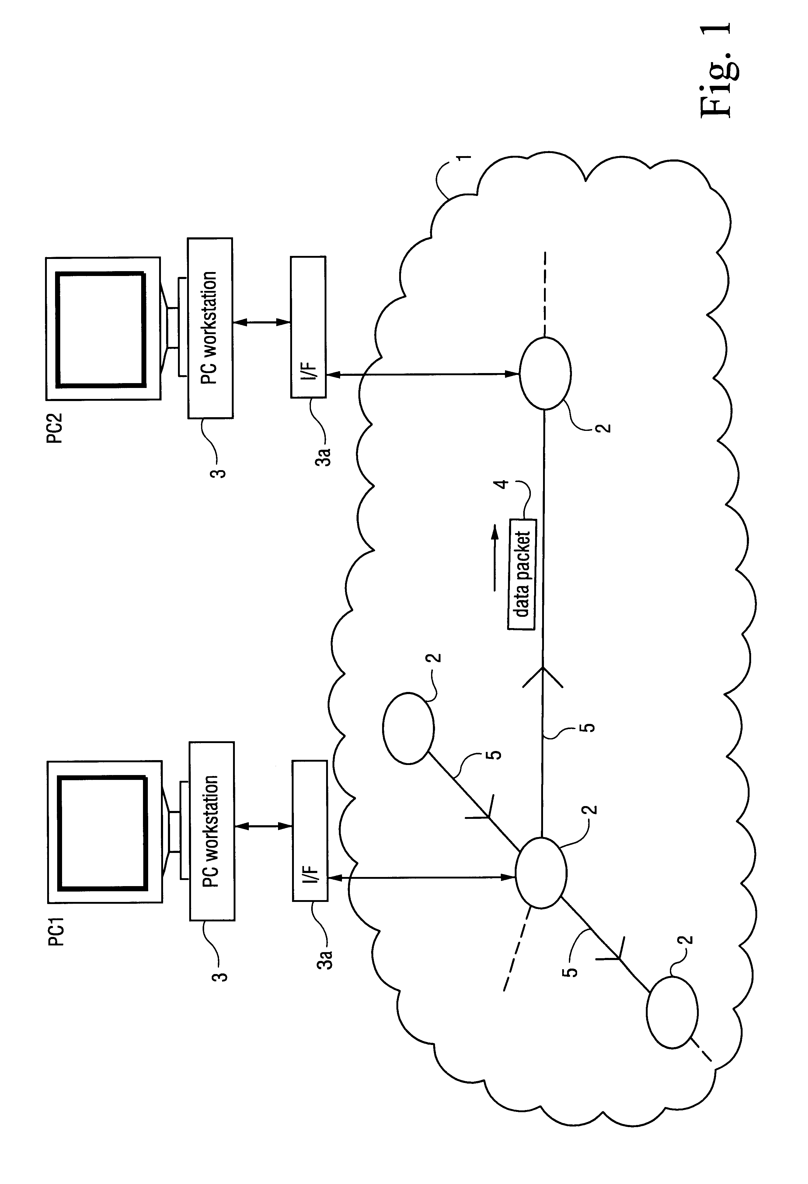
With reference to FIG. 1, an optical communications network comprises a LAN 1 linking a number of personal computer workstations 3. Each workstation is connected to the LAN via a network interface 3a. The workstations and LAN together provide a visualisation of complex data. Each workstation is connected to a respective node 2 of the network. Packets of data 4 are communicated between the workstations 3 via the nodes 2 and links 5. In this example, the links 5 are formed from optical fibre and transmit the packets 4 in the optical domain.

Although, for ease of illustration, only a few nodes are shown in the FIGURE, in practice, the network may comprise many hundreds of nodes.

In this first example, the nodes and the interconnecting fibres are configured as an n.times.n torus network.

The n.times.n torus network is a regular network with unidirectional links, and the nodes have indegree and outdegree of 2. Logically, the links form a grid on the surface of a torus, and all the links in ...


PUM


Abstract

A communications network, suitable, for example, for linking computer processors, is formed from a number of nodes and links. The nodes and links are configured as a multiplicity of directed trails. Each directed trail spans some only of the nodes, but in combination the directed trails span every node of the network. Packets are routed through the network by selecting the appropriate one of the directed trails which links the source node and destination node, and by outputting the packet at the source node onto the selected trail. The nodes throughout the network may switch between predetermined and prescheduled switching states, and a given trail may be selected by choosing appropriately the time slot in which the packet is put onto the network. The network may be a photonic network carrying optical packets.

Description

BACKGROUND TO THE INVENTION1. Field of the Invention2. Related ArtThe present invention relates to a communications network, and in particular to the routing of packets in a network.There is a need for high speed packet networks for use, for example, in local area networks for interconnecting computer systems, or for use as part of the internal infrastructure of a multiprocessor computer. It has been proposed to implement such networks using ultrafast photonic technology. In implementing the network, the provision of an appropriate routing mechanism for the packets has proved to be a particularly critical design problem. There are a number of potentially conflicting requirements which have to be satisfied by any routing mechanism. In particular, it is desirable that the processing overhead at each node should be kept low: otherwise, the time required to process the packet limits the throughput of the node and hence of the network. However, it is also desirable to ensure that the rou...

Claims


Application Information

Patent Timeline
IPC IPC(8): H04L12/56H04M3/00H04L45/02H04L45/16H04Q11/00H04Q11/04
CPCH04L45/02H04L45/16H04Q11/0005H04Q2011/0024H04Q2011/0033H04Q2011/0039H04Q2011/0052H04Q2011/0073H04Q2011/009
Inventor COTTER, DAVID
Owner BRITISH TELECOMM PLC
Why Eureka
Try Eureka