Melting of glass

a technology of glass and glass sintering, which is applied in the direction of glass rolling equipment, glass making equipment, manufacturing tools, etc., can solve the problems of fuel combustion in air, formation of foam on the surface of glass, and increase of water (steam) in the furnace atmospher

Inactive Publication Date: 2004-04-06
PILKINGTON PLC
View PDF6 Cites 80 Cited by
  • Summary
  • Abstract
  • Description
  • Claims
  • Application Information

AI Technical Summary

Benefits of technology

By using such a flame, we are able to remove most if not all of the foam and reduce the bubbles in the resultant glass to commercially acceptable levels for general glazing or even automotive glazing. Use of the invention permits oxy-fuel firing to be used as the sole heat source in a flat glass furnace rather than, as at present, only for boost heating in combination with other firing techniques.

Problems solved by technology

For many years, the fuel has been combusted in air.
Combustion of the fuel in oxygen as opposed to air results in an increase in the proportion of water (steam) in the furnace atmosphere, leading to the formation of a foam lying on the surface of the glass.
However, it is unacceptable in flat glass production, where the molten glass is drawn off from the surface of the melt and the acceptable bubble limits are usually about two orders of magnitude below those acceptable in container glass production.
However, because the chief reason for the provision of such ports is to attack the foam, it is not particularly useful to have such burner arrangements in regions where the foam is not a problem.
However, one or more additional firing burners or pair of firing burners may be provided downstream of any burners dispersing the foam provided such burner or burners do not give rise to unacceptable foam.

Method used


Image

  • Melting of glass
  • Melting of glass
  • Melting of glass

Examples


Embodiment Construction

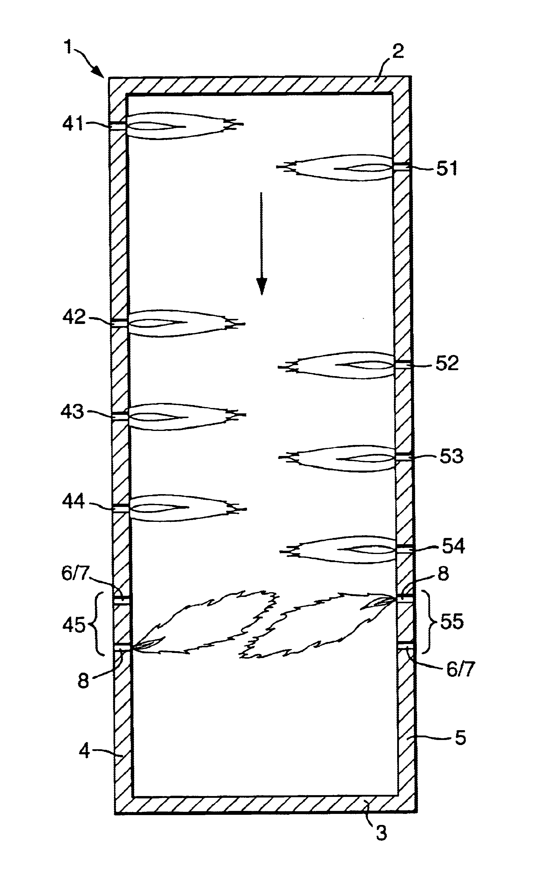
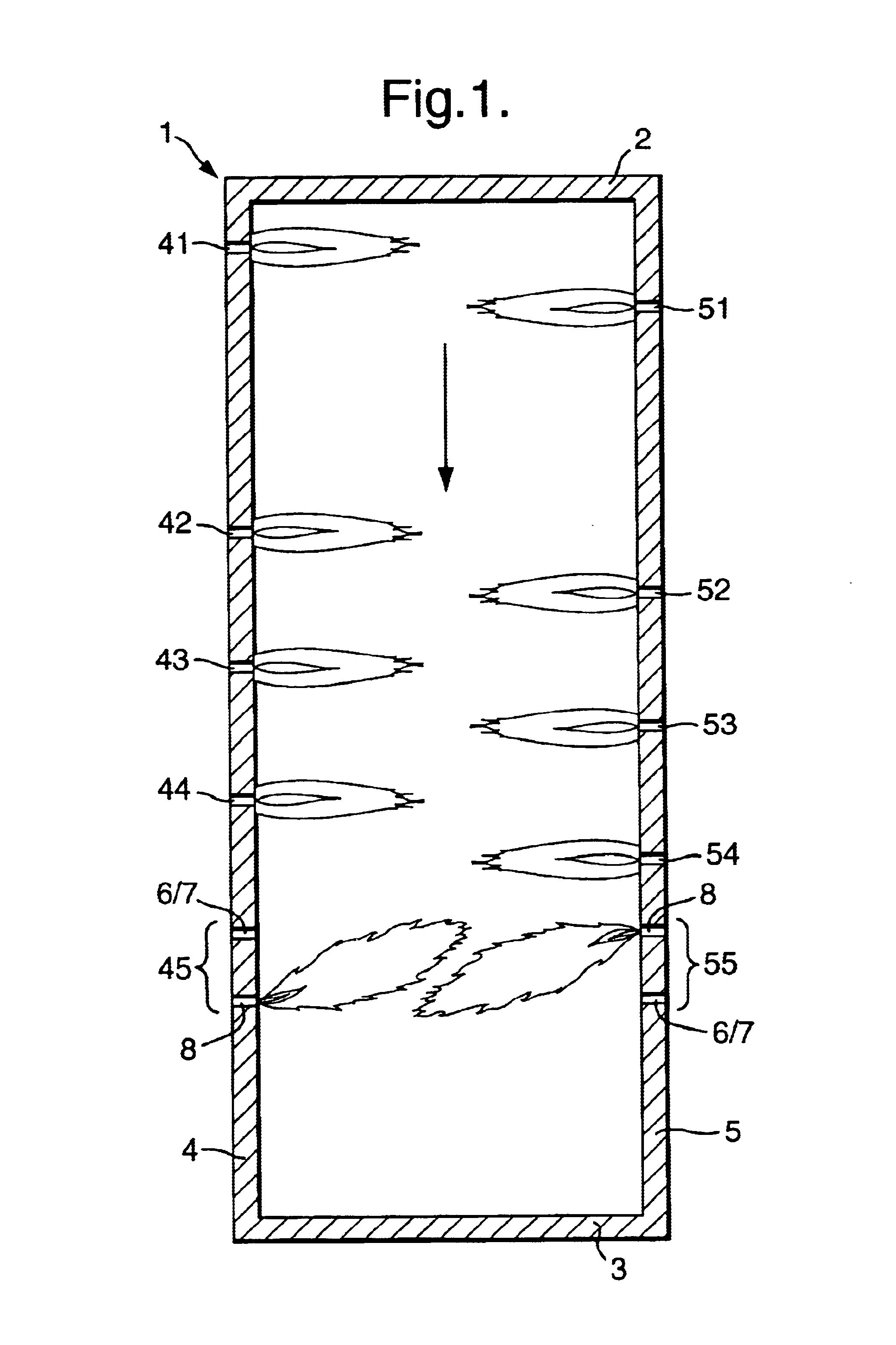
Referring to FIG. 1, a float glass melting furnace, which may be gas fired or oil fired, generally designated 1, has an upstream end 2 where the glass batch components for melting are fed in and a downstream end 3 from which the molten glass is fed through a float glass canal to a float bath where it is formed into a ribbon of glass. The ribbon cools as it progresses along the bath and, when it has cooled sufficiently, it is removed from the bath and passed through an annealing lehr to a warehouse end where it is cut into individual plates which are removed from the line and stored for distribution and use.

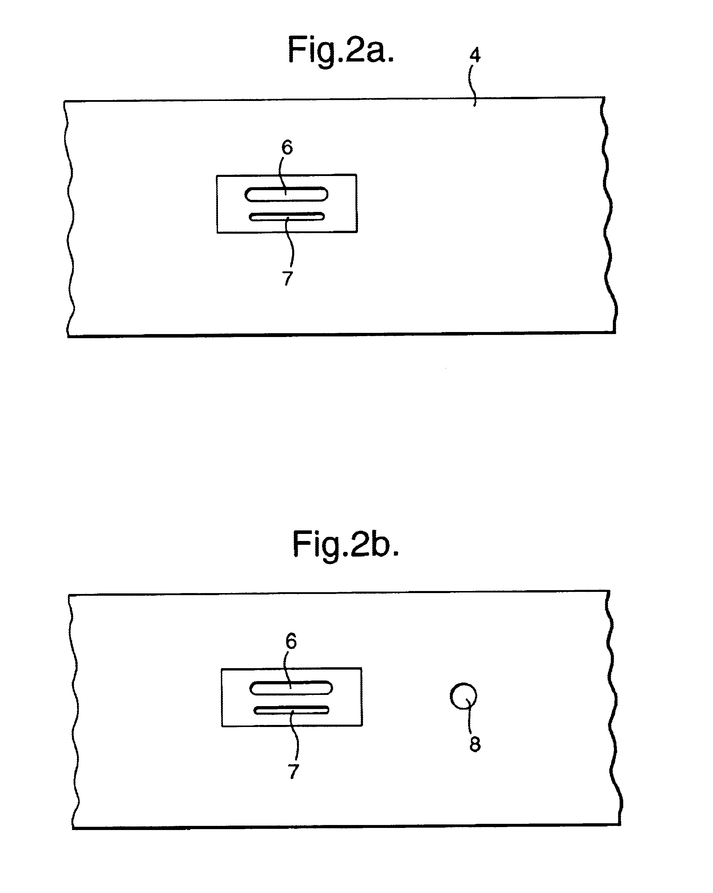
The furnace 1 has opposed side walls 4 and 5 each provided with exhaust ports (not shown) for waste gases, including combustion gases, towards the upstream end of the furnace.

A row of five spaced apart burners 41-45 and 51-55 is provided on each side of the furnace, the burners of one side of the furnace being staggered in relation to the burners on the other side of the furnace. ...


PUM

PropertyMeasurementUnit
thicknessaaaaaaaaaa
luminescentaaaaaaaaaa
lengthaaaaaaaaaa

Abstract

A method of producing flat glass in which foam which appears on the surface of molten glass melted using oxy-fuel burners is dispersed by directing a diffuse, luminescent flame onto the surface of the glass carrying the foam.

Description

1. Field of the InventionThe present invention relates to a method of melting of glass for the production of flat glass, and to an apparatus for use in that method.2. Description of the Prior ArtThe batch constituents used for making glass are melted by means of burners which may be disposed in a variety of configurations. Probably the most common burner arrangement is one in which fossil fuel fired burners are disposed opposite one another along the length of a melting area of the furnace. For many years, the fuel has been combusted in air. More recently, however, so-called `oxy-fuel` firing has been employed, primarily in container glass furnaces. In such a system the fuel is supplied together with oxygen (rather than air). In one particular arrangement that is known, the fuel and oxygen are supplied through co-axial conduits.In oxy-fuel firing, the oxygen and the fuel are mixed as soon as they issue from their feed conduits into the furnace and, as a result, the oxygen-fuel mixtu...

Claims


Application Information

Patent Timeline
Patent Type & Authority Patents(United States)
IPC IPC(8): C03B5/00C03B5/235C03B5/20
CPCC03B5/202C03B5/2353Y02P40/50Y02P40/57
Inventor BARROW, THOMASBIRD, DAVID ALAN
Owner PILKINGTON PLC
Why Eureka
Try Eureka