Eureka AIR delivers breakthrough ideas for toughest innovation challenges, trusted by R&D personnel around the world.

Printing bridge for silk-screen printing machines

a printing bridge and silk screen technology, applied in printing presses, rotary presses, printing presses, etc., can solve the problems of difficult automatic movement of retaining elements, and achieve the effect of reducing the setup time of the machin

Inactive Publication Date: 2004-04-06
ARGON HT
View PDF6 Cites 0 Cited by
  • Summary
  • Abstract
  • Description
  • Claims
  • Application Information

AI Technical Summary

Benefits of technology

One purpose of the present invention is to furnish a printing bridge for silk-screen printing machines, either automatic or semiautomatic, which easily allows the employment of computer-controlled motive means to move the retaining elements along the transverse beam. Another purpose of the present invention is to furnish a printing bridge that allows the precise positioning of the doctor along the transverse beam and reduces the setup time of the machine during the job changeover.
And a further purpose of the present invention is to furnish a printing bridge that is simple to produce and adaptable to different demands of printing jobs.

Problems solved by technology

In particular, this sliding of the retaining elements of the doctor along the transverse support beam is effected manually since it is not simple to produce an automatic means for the movement of the retaining elements.
The mutual interference between the means of movement of the different retaining elements, together with the crossover of the same means of movement with the flexible compressed air distribution tubes, makes it difficult to employ automatic means to move such retaining elements.

Method used


Image

  • Printing bridge for silk-screen printing machines
  • Printing bridge for silk-screen printing machines
  • Printing bridge for silk-screen printing machines

Examples


Embodiment Construction

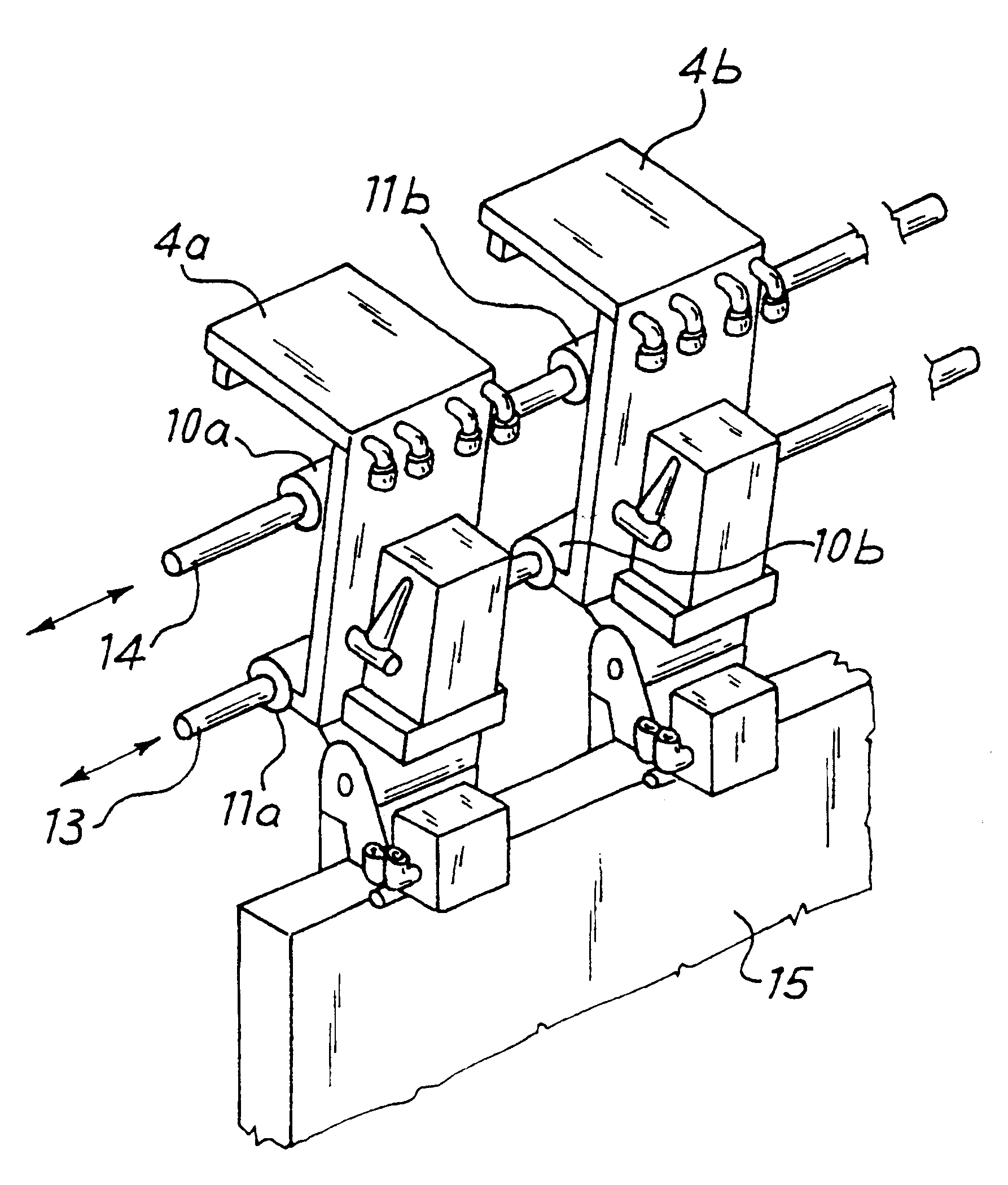
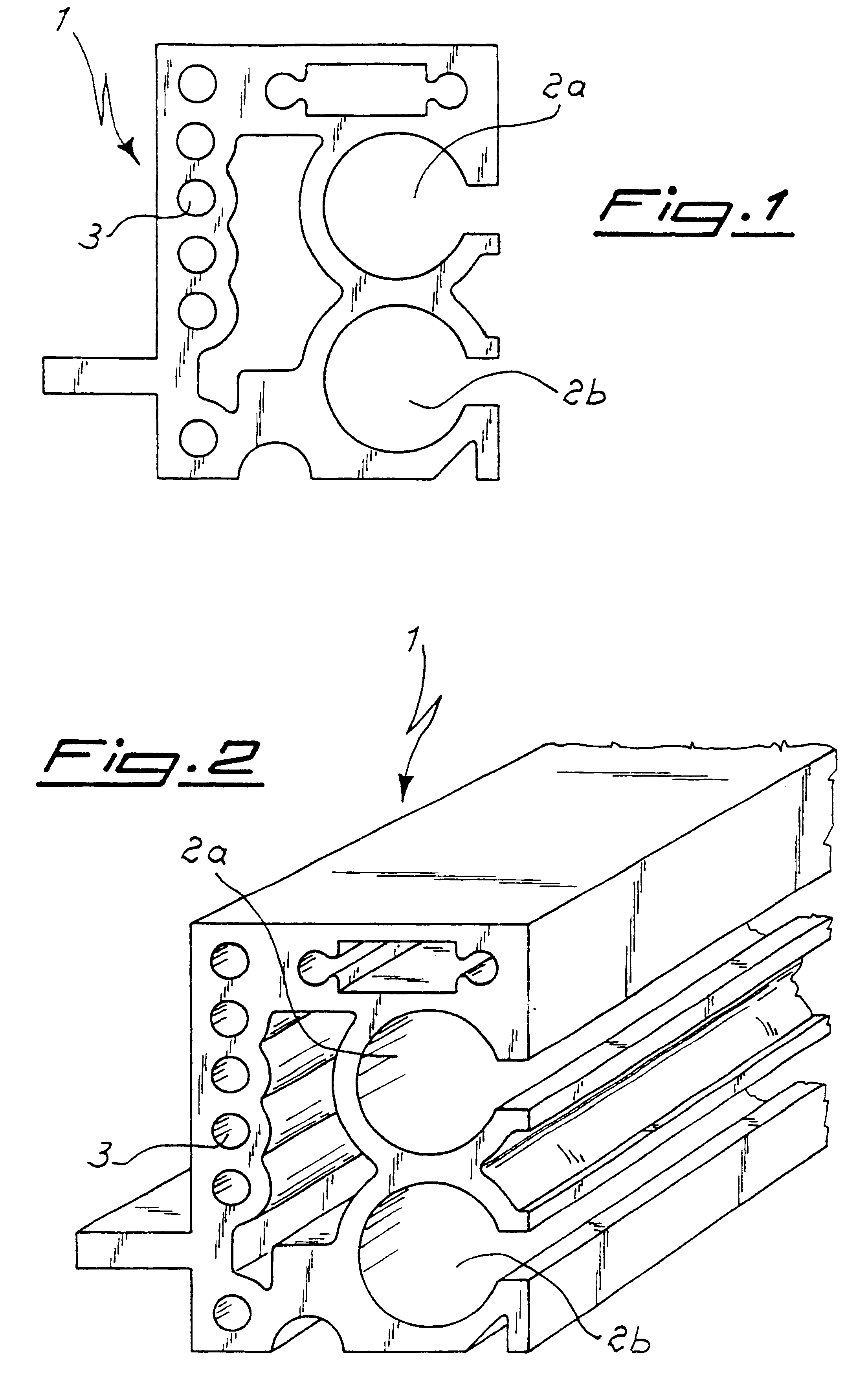
With reference to the FIGS. 1 and 2, the printing bridge of a silk-screen printing machine, according to the present invention; comprises a mobile transversal beam comprising a section bar 1 that presents through longitudinal holes 3 and two through cylindrical slots 2a and 2b. The section bar 1 extends for the whole width of the printing bridge and houses a doctor retaining element 4.

Such section bar 1, preferably produced in aluminum, is particularly rigid and can therefore be employed for silk-screen printing machines having printing bridges of considerable width, without the bending of the same section bar jeopardizing the quality of the printing.

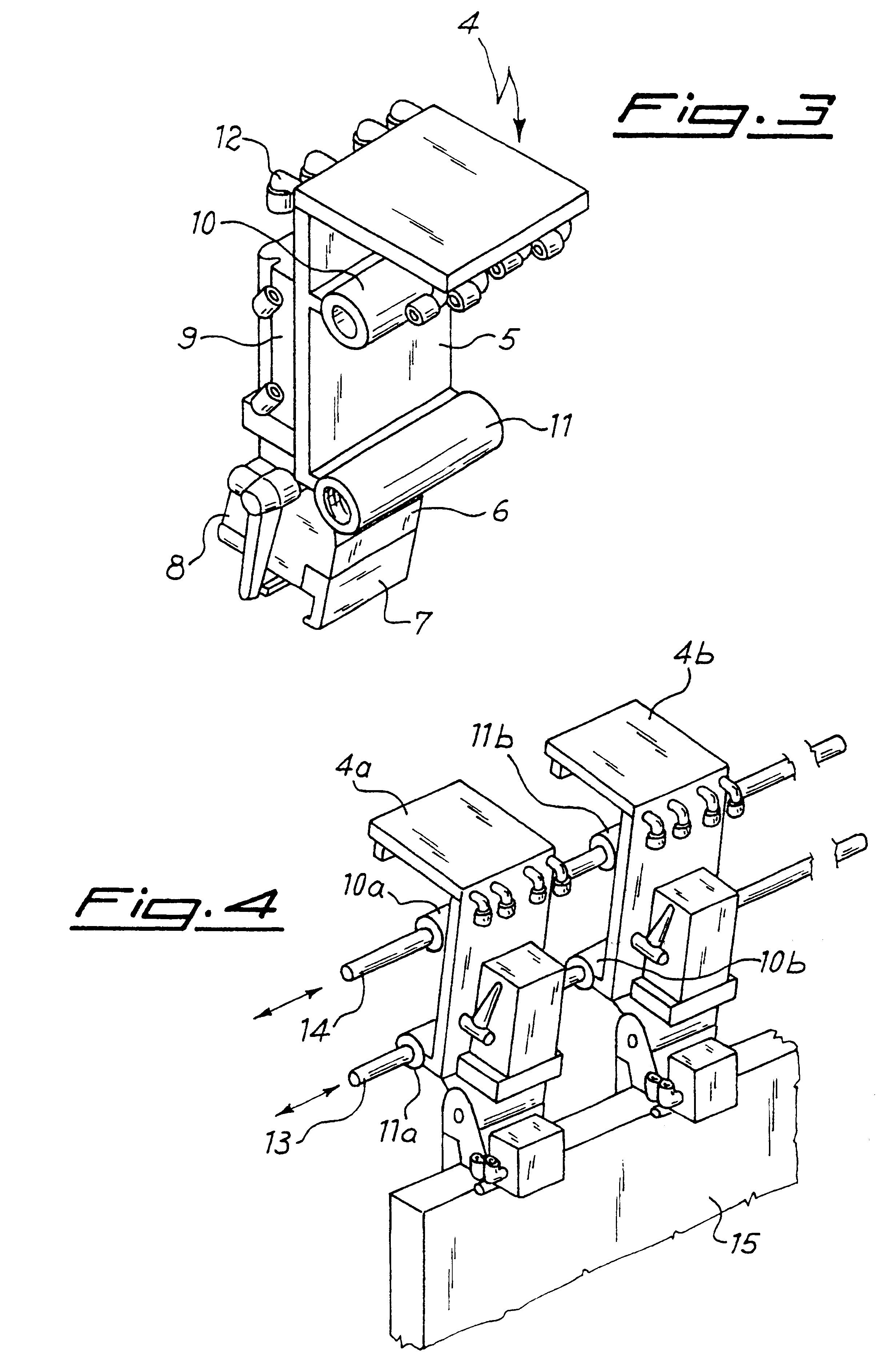
The retaining element 4, as illustrated in FIG. 3, comprises an upper body 5 and a lower assembly 6 to support the doctor and to press the same against the semi-permeable form. The assembly 6 is endowed with jaws 7 that are closed or separated reciprocally by a pneumatic actuator 8 to retain and release the doctor. The assembly 6, furth...


PUM


Abstract

A printing bridge for silk-screen printing machines has at least one mobile transversal support beam and a doctor retaining and adjusting element slidably attached to the beam. In order to deliver fluid to the doctor retaining and adjusting element, the doctor retaining and attaching element includes a fluid driven actuator connected by tubes to a duct in a section bar on the transversal support beam.

Description

The present invention relates to a printing bridge for silk-screen printing machines, of the type comprising at least one mobile transversal support beam and one or more elements acting to retain a doctor mounted in a sliding way on the same transversal support beam.STATE OF THE ARTGenerally, silk-screen printing machines comprise a lower frame designed to support and operate the surface to be printed, such as sheets for the printing of posters for instance, a semi-permeable elastic form located in correspondence of the surface, and an upper printing bridge equipped with a mobile transversal beam to which doctor retaining elements are linked in a sliding way. During printing, the doctor is pressed onto the inked semi-permeable form against the surface to be printed and is moved with respect to the form by the transverse beam, to allow the deposition of the ink on the same surface. This set of operations is almost totally automated in modern silk-screen printing machines.In particula...

Claims


Application Information

Patent Timeline
Patent Type & Authority Patents(United States)
IPC IPC(8): B41F15/14B41F15/46
CPCB41F15/46
Inventor MANOUKIAN, HARUTIUN
Owner ARGON HT
Why Eureka
Eureka Blog
Learn More