Method of joining mirrors to ring laser gyro block assemblies

a laser gyroscope and mirror technology, applied in the direction of lasers, optical resonator shapes and construction, instruments, etc., can solve the problems of gyroscope failure, gyroscope operation failure, and lower limi

Inactive Publication Date: 2004-04-27
HONEYWELL INT INC
View PDF10 Cites 22 Cited by
  • Summary
  • Abstract
  • Description
  • Claims
  • Application Information

AI Technical Summary

Problems solved by technology

Unfortunately, the epoxy and soft metal bonding techniques, due to the flexibility of the bond materials, tend to allow outgassing or fail to provide a bond capable of withstanding the pressures typically required for high-end gyroscopes.
Indium, in particular, extrudes out of the bonding area with repeated use of the device, eventually causing failure of the gyroscope.
Neither epoxy nor soft metal allow the gyroscope to be operated at high temperatures, since the limit of a gyroscope's range of operation is the melting temperature of the bonding material.
In some cases, an even lower limit results if the bonding material begins to degrade below its melting temperature.
Unfortunately, the glass frit bonding process requires an elevated temperature which substantially limits the types of processing which can be done near the area of the bond prior to the bonding process.
Thus, use of frits usually introduces a thermal mismatch into the gyroscope since a compromise must be made between bonding temperature and the CTE of the frit.
Applying the fluid adhesive to the interface may cause it to wick into the interface.

Method used


Image

  • Method of joining mirrors to ring laser gyro block assemblies
  • Method of joining mirrors to ring laser gyro block assemblies
  • Method of joining mirrors to ring laser gyro block assemblies

Examples


Embodiment Construction

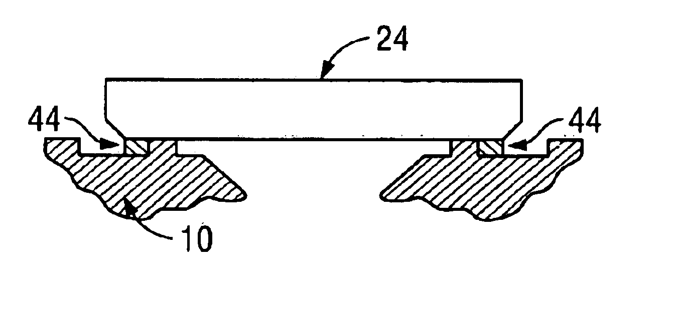
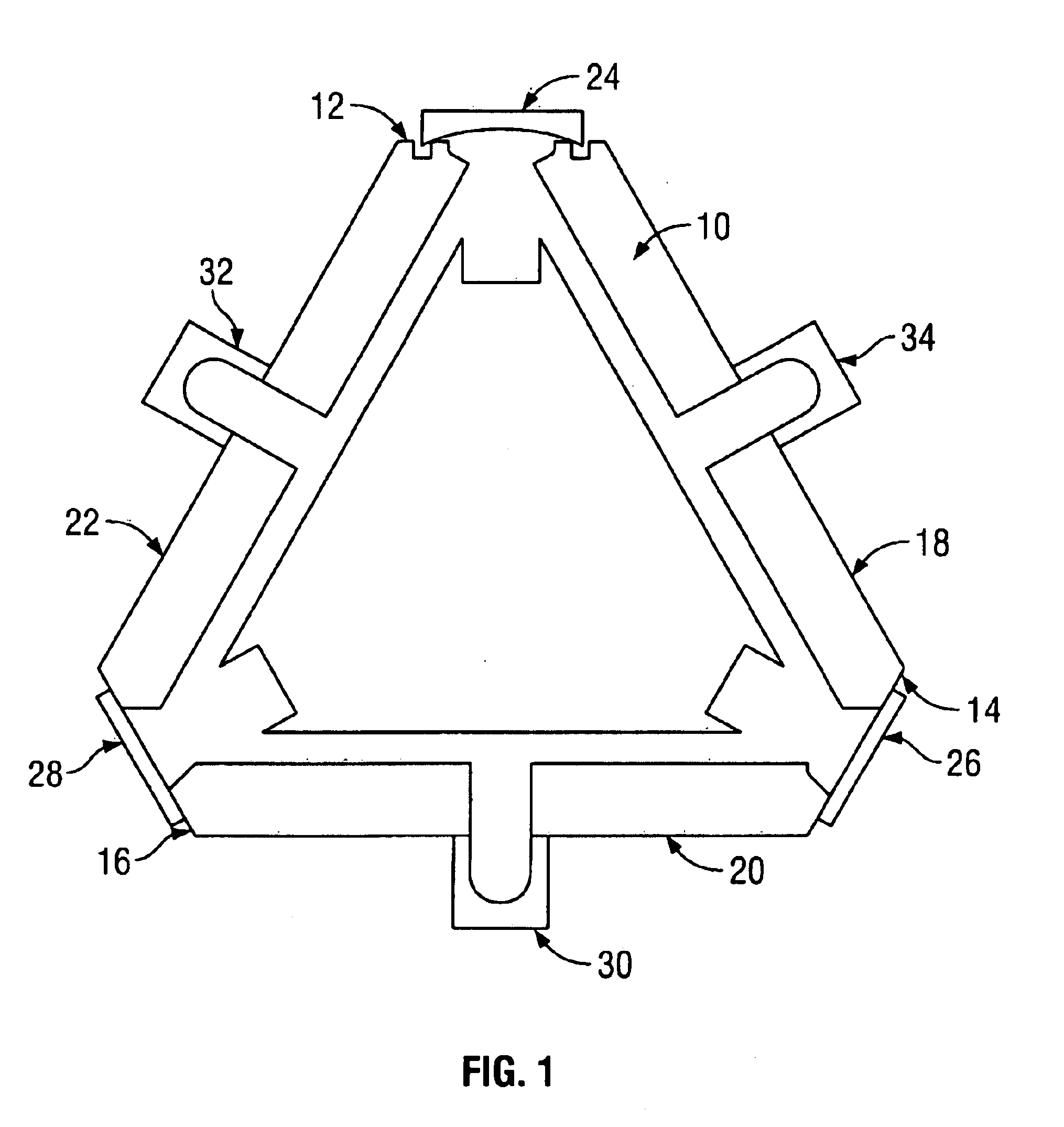
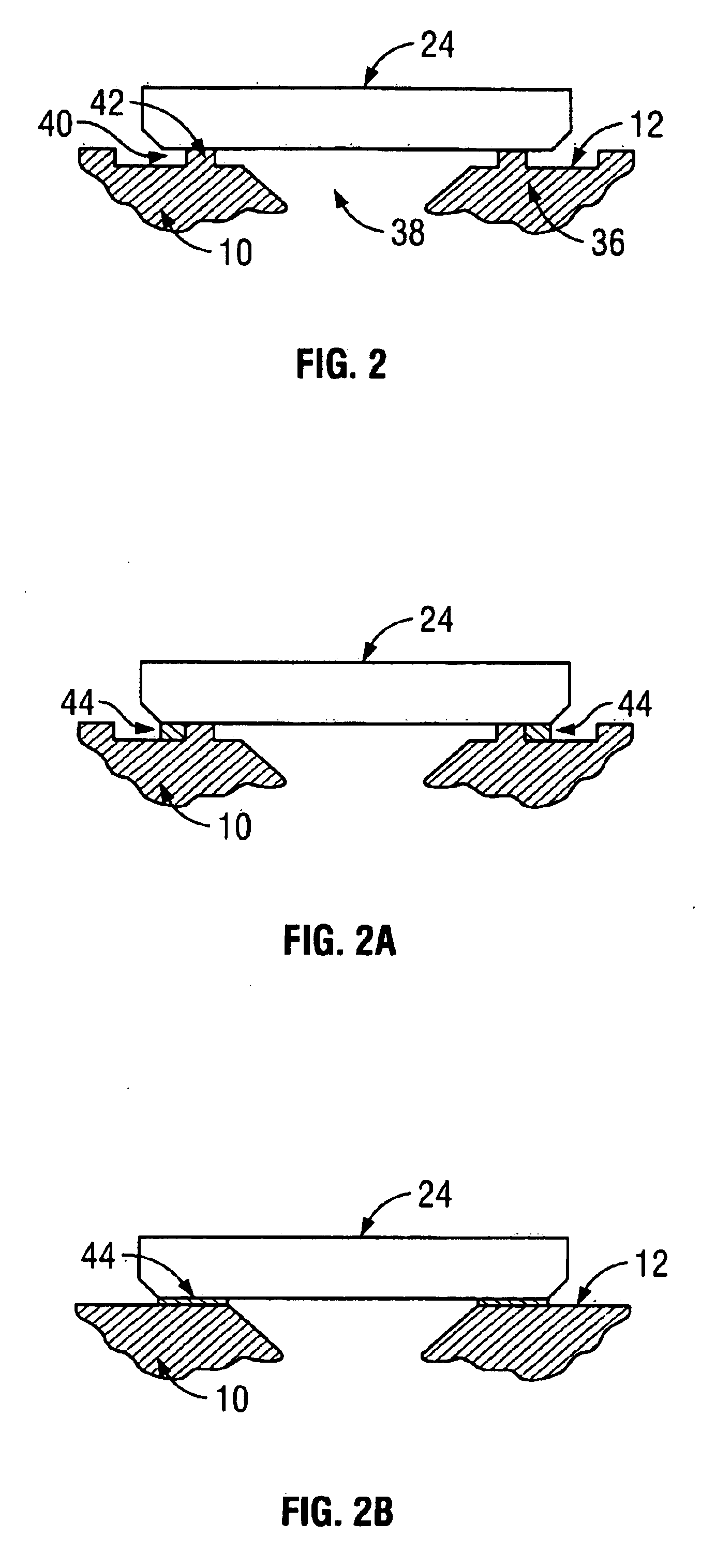
As described above, currently used methods and materials for attaching components to ring laser gyro blocks have distinct disadvantages, among them the need for labor-intensive preparation, and for high-temperature processing that may be harmful to some gyro components (which may also cause manufacturers to further restrict processing). Also, some bonds, such as those made at lower temperatures, may have shorter life cycles than other bonds.

Accordingly, exemplary and alternative exemplary embodiments of the present invention provide a method for attaching and sealing components to ring laser gyro blocks using a process that requires temperatures only somewhat higher (if at all) than room temperature, and that produces long-lasting hermetic seals that can withstand high temperatures. These advantages can be realized by allowing a fluid or gel adhesive to wick into the component-to-block interface. One adhesive that can be used is an aqueous sodium silicate, which hardens into a glass...


PUM


Abstract

A method of attaching at least one component to a ring laser gyro block. The method may include positioning the component so that a mounting surface of the at least one component is substantially parallel to a mounting surface of the ring laser gyro block and applying a fluid adhesive to the exposed interface of the mounting surface of the at least one component and the mounting surface of the ring laser gyro block. The method also includes allowing the fluid adhesive to harden.

Description

1. Field of the InventionThis invention relates generally to bonding methods for use with materials such as glass, quartz, metal, ceramic and the like. More specifically, the invention relates to a method for bonding ring laser gyroscope mirrors to bodies of ring laser gyroscopes.2. Description of Related ArtIn one common form of compact ring laser gyroscope, a block comprising a glass, quartz, ceramic or similar material and having a low coefficient of thermal expansion (CTE) forms the body of the gyroscope. A number of components, typically composed of glass or metal, such as electrodes, mirrors, and readout apparatus, are attached to the gyroscope body. Sealed passages in the body allow communication among the various components. The passages of the gyroscope body are filled with a lasing gas that lases when current is applied to the gyroscope.A cathode and two anode components are used to apply current; they are designed to create beams of laser light that travel in opposite dir...

Claims


Application Information

Patent Timeline
Patent Type & Authority Patents(United States)
IPC IPC(8): G01C19/66G01C19/64H01S3/081H01S3/083
CPCG01C19/661H01S3/083H01S3/0835
Inventor THORLAND, RODNEY H.OSTERTAG, TOMOLLESTAD, RONBECKWITH, TIM
Owner HONEYWELL INT INC
Why Eureka
Try Eureka