Fiber optic curvature sensor for towed hydrophone arrays

a technology of curvature sensor and hydrophone array, which is applied in the direction of optics, optical elements, instruments, etc., can solve the problems of unsuitability in the current environment, high cost of sensors, and light loss

Inactive Publication Date: 2004-04-27
THE UNITED STATES OF AMERICA AS REPRESENTED BY THE SECRETARY OF THE NAVY
View PDF8 Cites 20 Cited by
  • Summary
  • Abstract
  • Description
  • Claims
  • Application Information

AI Technical Summary

Benefits of technology

It is yet a further object of the present invention to provide a sensor system as above which achieves high strain sensitivity while limiting the maximum strain seen by the optical fiber(s) therein so that only the operational dynamic range is required of the optical fiber(s).

Problems solved by technology

Bending of the fiber results in light loss through a surface strip or band, along one side of the fiber, this loss being detected.
One of the deficiencies of these systems however is that the optical fiber(s) used in the sensor is / are attached directly to the structure whose behavior is being observed.
Such sensors are quite expensive.
They are unsuitable in today's environment where one needs to reduce cost in a towed array.
However, the strain seen in the hose wall as the array passes over small diameter handling sheaves can exceed the survival strain of an optical fiber.
It has been suggested to reduce the strain seen by winding at a pitch angle, but that approach is awkward.
The disadvantage of all these mounting schemes is that while limiting the maximum strain seen, these schemes also limit the strain sensitivity achievable.

Method used


Image

  • Fiber optic curvature sensor for towed hydrophone arrays
  • Fiber optic curvature sensor for towed hydrophone arrays
  • Fiber optic curvature sensor for towed hydrophone arrays

Examples


Embodiment Construction

)

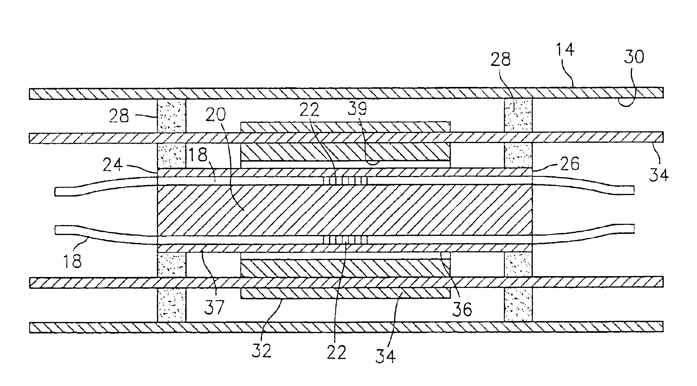
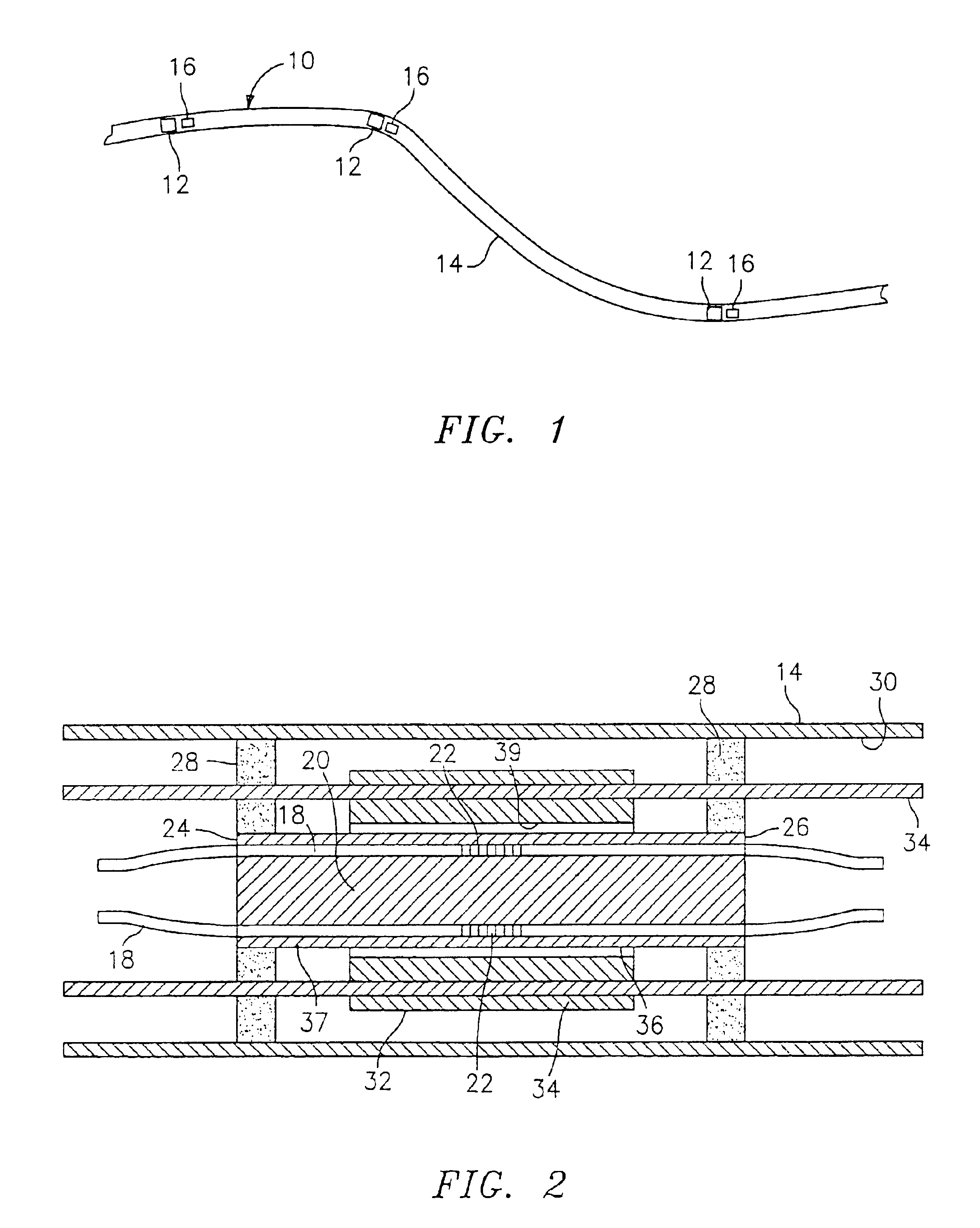
Referring now to the drawings, FIG. 1 illustrates a system 10 for sensing the curvature and shape of a towed array. Instead of a continuous optical fiber embedded into the hose wall of the array, the system 10 has a plurality of single point curvature sensors 12 placed at various locations along the length of the towed hydrophone array 14. As depicted in FIG. 1, the curvature sensors 12 may be placed quite far apart because of the long transverse wavelengths of the tow cables under tow. As a result, the system 10 requires fewer curvature sensors 12. The system 10 further has a plurality of roll sensors 16 with each roll sensor 16 being in close proximity to each curvature sensor 12 so that the direction of curvature relative to the surrounding environment may be determined. Because the curvature sensors 12 are single point sensors, the optical fiber(s) 18 that lead to and from each curvature sensor 12 may be separated from the structure of the towed hydrophone array 14 so that the ...


PUM


Abstract

The present invention relates to a system for sensing the curvature of a towed hydrophone array and a curvature sensor used in the system. The system has at least two curvature sensors positioned along the length of the array. Each of the curvature sensors comprises a bend member which bends as the array bends, at least one optical fiber within the bend member, and at least one detection device embedded within the at least one optical fiber to detect a change in the strain in the at least one optical fiber.

Description

(1) Field of the InventionThe invention relates to a device and method for sensing the curvature of a towed array. The device of the present invention, in combination with other sensors, may be used to determine the shape of a towed hydrophone array.(2) Description of the Prior ArtOptical fibers have been used in a variety of sensors. For example, U.S. Pat. Nos. 4,654,520; 4,812,645; and 4,927,232, all to Griffiths, illustrate structural monitoring systems which have an optical fiber securely and continuously fastened to a structure such as a pipeline, offshore platform, bridge, building, or a dam or to a natural object. A light signal is passed into one end of the optical fiber. Any physical movement of the structure, or sectional movements along the optical fiber path, such as deflection, bending, displacement, or fracture of the structure affects the optical fiber. As a consequence, detectable changes occur in the electro-optical signature or in the light signal transmission.U.S....

Claims


Application Information

Patent Timeline
Patent Type & Authority Patents(United States)
IPC IPC(8): G01D5/353G01D5/26G01V1/16G01V1/20
CPCG01D5/35303G01V1/201
Inventor AMES, GREGORY H.DEUS, III, ANTONIO L.
Owner THE UNITED STATES OF AMERICA AS REPRESENTED BY THE SECRETARY OF THE NAVY
Why Eureka
Try Eureka