Strain sensor and method of fabricating the same

a technology of strain sensor and fabrication method, which is applied in the direction of piezo-resistive material force measurement, instrumentation, force measurement apparatus for force/torque/work measurement, etc., can solve the problems of low electrical conductivity, difficult to accurately detect strain information, and opaque conventional nanoparticle-based strain gauges, etc., to achieve the effect of improving the sensitivity of the strain sensor

Active Publication Date: 2020-08-13
KOREA UNIV RES & BUSINESS FOUND
View PDF10 Cites 2 Cited by
  • Summary
  • Abstract
  • Description
  • Claims
  • Application Information

AI Technical Summary

Benefits of technology

[0013]Therefore, the present disclosure has been made in view of the above problems, and it is an object of the present disclosure to provide a strain sensor including an X-axis sensor and a Y-axis sensor including a metal-insulator heterostructure composed of first nanocrystals used as a metallic material and second nanocrystals used as an insulating material. With this configuration, the sensitivity of the strain sensor may be improved using percolation.

Problems solved by technology

However, carbon-based materials have low gauge factors (GFs) and low electrical conductivity, which may cause problems.
When a gauge factor is low, accurate detection of information about strain is difficult.
However, conventional nanoparticle-based strain gauges are opaque, and the aesthetics thereof are poor.
Accordingly, the conventional nanoparticle-based strain gauges are not suitable for use as a wearable device.
In addition, since the sensitivity of the conventional nanoparticle-based strain gauges is very low, the strain gauges have difficulty in reading minute body signals such as blood pressure and breathing.
In addition, the conventional strain gauges have a limitation in that the strain gauges can only detect strain in the uniaxial direction.
However, the strain sensor including a nanowire has a limitation in that the strain sensor can only detect strain in one specific direction.
However, conventional strain sensors are sensitive to strain occurring in one direction and, as such, the conventional strain sensors have difficulty in accurately detecting multidimensional and random strain.

Method used


Image

  • Strain sensor and method of fabricating the same
  • Strain sensor and method of fabricating the same
  • Strain sensor and method of fabricating the same

Examples


Embodiment Construction

[0057]In the following description of the present disclosure, a detailed description of known functions and configurations incorporated herein will be omitted when it may make the subject matter of the present disclosure unclear. The terms used in the specification are defined in consideration of functions used in the present disclosure, and can be changed according to the intent or conventionally used methods of clients, operators, and users. Accordingly, definitions of the terms should be understood on the basis of the entire description of the present specification.

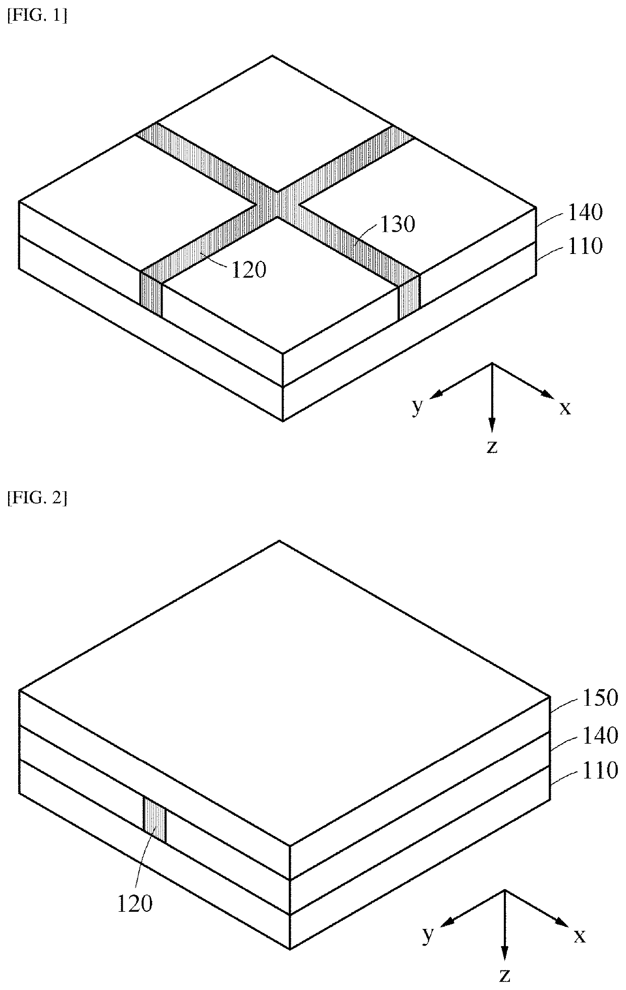
[0058]FIGS. 1 and 2 each show a three-dimensional shape of a strain sensor according to an embodiment of the present disclosure.

[0059]The strain sensor according to an embodiment of the present disclosure includes an X-axis sensor 120 formed on a flexible insulating substrate 110 and responsible for sensing X-axis strain, a Y-axis sensor 130 formed on the flexible insulating substrate 110 to be orthogonal to the X-axis...


PUM

PropertyMeasurementUnit
volume ratioaaaaaaaaaa
diameteraaaaaaaaaa

Abstract

The present disclosure discloses a strain sensor and a method of fabricating the same. The strain sensor according to an embodiment of the present disclosure includes an X-axis sensor formed on a flexible insulating substrate and responsible for sensing X-axis strain; a Y-axis sensor formed on the flexible insulating substrate to be orthogonal to the X-axis sensor and responsible for sensing Y-axis strain; a metal electrode formed on a region of the flexible insulating substrate where the X-axis sensor and the Y-axis sensor are not formed; and an encapsulation layer formed on the X-axis sensor, the Y-axis sensor, and the metal electrode. In this case, the X-axis sensor and the Y-axis sensor have a metal-insulator heterostructure.

Description

CROSS-REFERENCE TO RELATED APPLICATION[0001]This application claims priority to Korean Patent Application No. 10-2019-0014455, filed on Feb. 7, 2019 in the Korean Intellectual Property Office, the disclosure of which is incorporated herein by reference.BACKGROUND OF THE DISCLOSUREField of the Disclosure[0002]The present disclosure relates to a strain sensor and a method of fabricating the same, and more particularly, to a metal-insulator heterostructure-based transparent multi-axis strain sensor and a method of fabricating the same.Description of the Related Art[0003]In general, a strain gauge or a strain sensor is used to convert a mechanical fine strain into an electrical signal and detect the electrical signal. More specifically, a strain sensor that measures strain such as tensile or compression of various structures including aircraft, automobiles, machine tools, bridges, ships, and the like enables effective performance of static and dynamic tests, structural stability tests, ...

Claims


Application Information

Patent Timeline
Patent Type & Authority Applications(United States)
IPC IPC(8): G01L1/22
CPCG01L1/2287G01L5/161G01L1/22G01B7/16G01P13/00C08L83/04C08L33/12C08L79/08C01G19/00C01G9/02C01P2002/60G01L1/18
Inventor OH, SOONG JULEE, WOO SEOKKIM, DONG GYU
Owner KOREA UNIV RES & BUSINESS FOUND
Why Eureka
Try Eureka