Unlock instant, AI-driven research and patent intelligence for your innovation.

Clutch assembly and methods of assembling and operating the same

a technology of multiple clutches and components, applied in the direction of friction clutches, mechanical actuated clutches, clutches, etc., can solve the problem of a friction clutch reversing the operating point in respons

Inactive Publication Date: 2004-05-04
LUK LAMELLEN & KUPPLUNGSBAU BETEILIGUNGS KG
View PDF4 Cites 20 Cited by
  • Summary
  • Abstract
  • Description
  • Claims
  • Application Information

AI Technical Summary

Benefits of technology

The clutch assembly maintains reliable and consistent operation throughout its lifespan by automatically adjusting for wear, reducing the need for manual adjustments and preventing damage from uneven wear, ensuring efficient torque transmission and extended clutch life.

Problems solved by technology

A drawback of conventional arrangements of such character is that the operating point of a friction clutch is shifted in response to wear in actual use of the friction clutches; this necessitates a change in the magnitude of the actuating force which must be applied in order to engage or disengage the clutches.

Method used


Image

  • Clutch assembly and methods of assembling and operating the same
  • Clutch assembly and methods of assembling and operating the same
  • Clutch assembly and methods of assembling and operating the same

Examples


Embodiment Construction

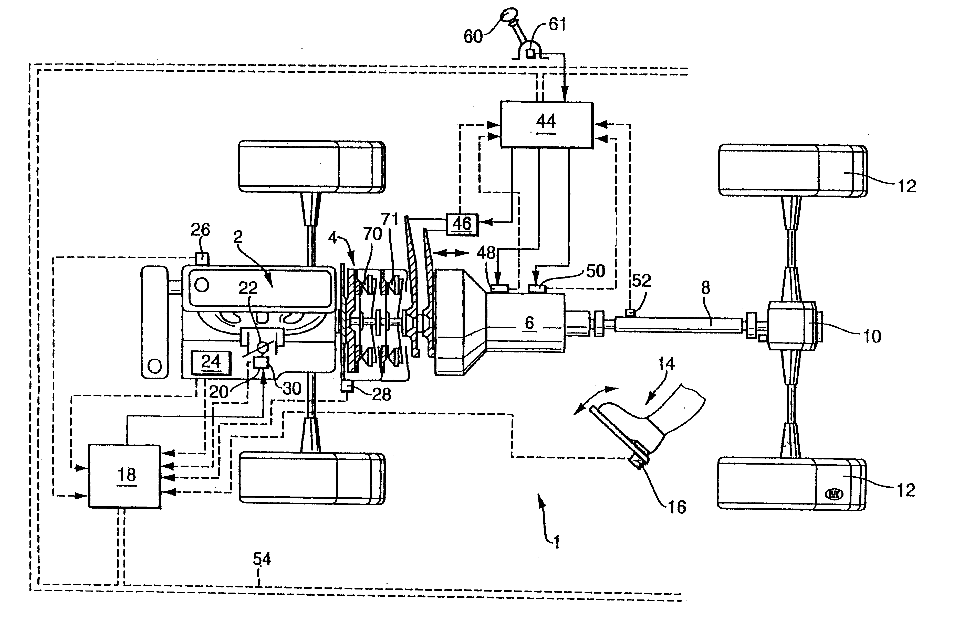
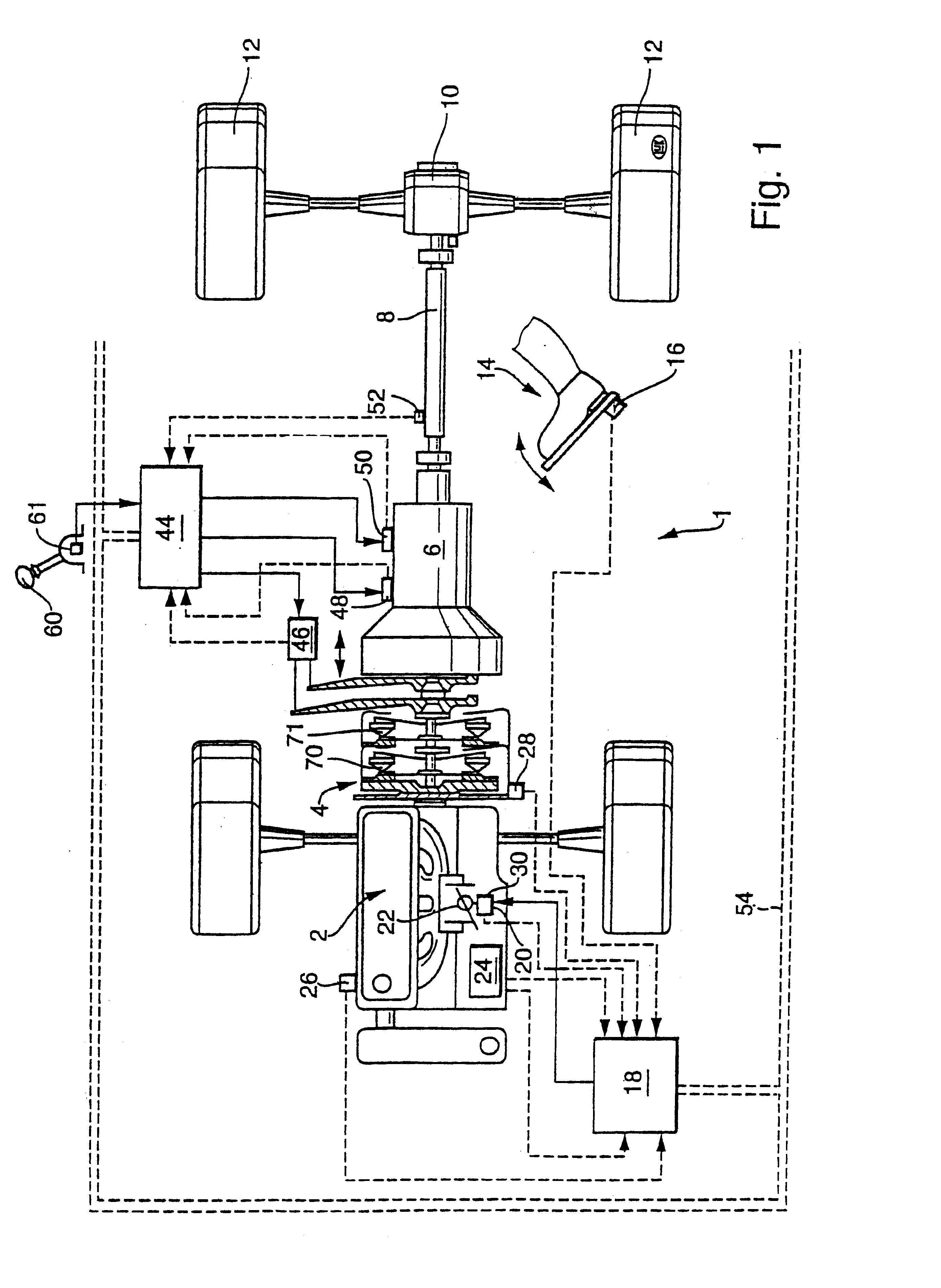
FIG. 1 shows a portion of a motor vehicle 1 having a power train including a prime mover 2 (the illustrated prime mover is an internal combustion engine), a change-speed transmission or gearbox 6 (hereinafter called gearbox), a clutch assembly 4 which is interposed between the output element of the engine 2 and the input shafts of the gearbox, and a Cardan shaft 8 which receives torque from the gearbox and can drive a differential 10. The latter can rotate the wheels 12 of the motor vehicle. It will be appreciated that the illustrated motor vehicle with two driven wheels 12 is but one example of motor vehicles which can be equipped with a power train embodying the present invention.

The character 60 denotes a speed or gear shifting lever which cooperates with a sensor 61 to transmit appropriate signals to a composite control unit 18, 44. This control unit can be replaced with a one-piece control unit; it is then possible to omit a CAN-bus 54 which is utilized in the illustrated power...


PUM


Abstract

First and second automatically operable friction clutches in the power train of a motor vehicle are connected between a rotary output element of the prime mover and first and second input elements of a change-speed gearbox. The wear upon the friction linings on the clutch disc of one of the clutches is frequently different from the wear upon the friction linings on the clutch disc of the other clutch. This is compensated for by automatically ascertaining the extent of wear upon the friction linings of the two clutches and by carrying out remedial undertakings such as temporarily reducing or interrupting the wear upon the friction linings which were subjected to more pronounced wear and / or increasing the wear upon the other friction linings.

Description

The present invention relates to clutches in general, and more particularly to improvements in clutch assemblies which can be utilized with advantage in the power trains of motor vehicles to transmit torque between a prime mover (such as an internal combustion engine, an electric motor or a hybrid drive) and a gearbox or transmission. Still more particularly, the invention relates to improvements in clutch assemblies which receive torque from the rotary output element of a prime mover (e.g., from the crankshaft or from the camshaft of an internal combustion engine) and can be operated to transmit torque to discrete first and second rotary input elements (e.g., to coaxial first and second shafts) of a gearbox.The invention also relates to methods of assembling and operating clutch assemblies of the above outlined character.It is already known to transmit torque between the prime mover of a motor vehicle and the gearbox in the power train of the vehicle by resorting to two friction cl...

Claims


Application Information

Patent Timeline
Patent Type & Authority Patents(United States)
IPC IPC(8): F16D13/58F16D21/00F16D21/06F16D13/75F16D13/46
CPCF16D13/757F16D21/06F16D2021/0646F16D13/75
Inventor BENETON, SEBASTIENRABER, CHRISTOPHERMEINHARD, ROLFBERGER, REINHARD
Owner LUK LAMELLEN & KUPPLUNGSBAU BETEILIGUNGS KG