Ballast for operating electric lamps

a technology for operating electric lamps and ballasts, which is applied in the direction of electric variable regulation, process and machine control, instruments, etc., can solve the problems that the voltage supply to the control device of the inverter is unsuitable for this purpose, and achieves low barrier-layer capacitance and low power loss.

Inactive Publication Date: 2004-05-04
ABL IP HLDG
View PDF9 Cites 25 Cited by
  • Summary
  • Abstract
  • Description
  • Claims
  • Application Information

AI Technical Summary

Benefits of technology

It is the object of the invention to provide for a generic ballast for the operation of electric lamps an improved voltage supply for the microcontroller which on the one hand reliably supplies the microcontroller with electrical energy, in particular even in the standby mode the ballast, and which on the other hand causes as little power loss as possible.
The ballast according to the invention has an inverter, a DC voltage supply circuit for the inverter, a load circuit, connected to the inverter, for supplying voltage to one or more electric lamps, a microcontroller for monitoring and controlling the operation of the ballast or the lamps and a voltage supply device for the microcontroller. According to the invention, the voltage supply device of the microcontroller is designed as a DC-DC converter, the voltage input of which is connected to the voltage output of the DC voltage supply circuit of the inverter and the voltage output of which is connected to the supply voltage input of the microcontroller. The DC-DC converter makes it possible to generate the supply voltage for the microcontroller directly from the AC line voltage rectified by the DC voltage supply circuit, to be precise independently of the operating state of the inverter and the lamps. What is more, the electrical power consumption of the ballast in the standby mode can be lowered to approximately 0.5 W.

Problems solved by technology

The device disclosed in the laid-open application EP 0 564 895 A1 for supplying voltage to the control device of the inverter is unsuitable for this purpose.

Method used


Image

  • Ballast for operating electric lamps
  • Ballast for operating electric lamps
  • Ballast for operating electric lamps

Examples


Embodiment Construction

The invention is explained in more detail below on the basis of a preferred exemplary embodiment. In the drawing:

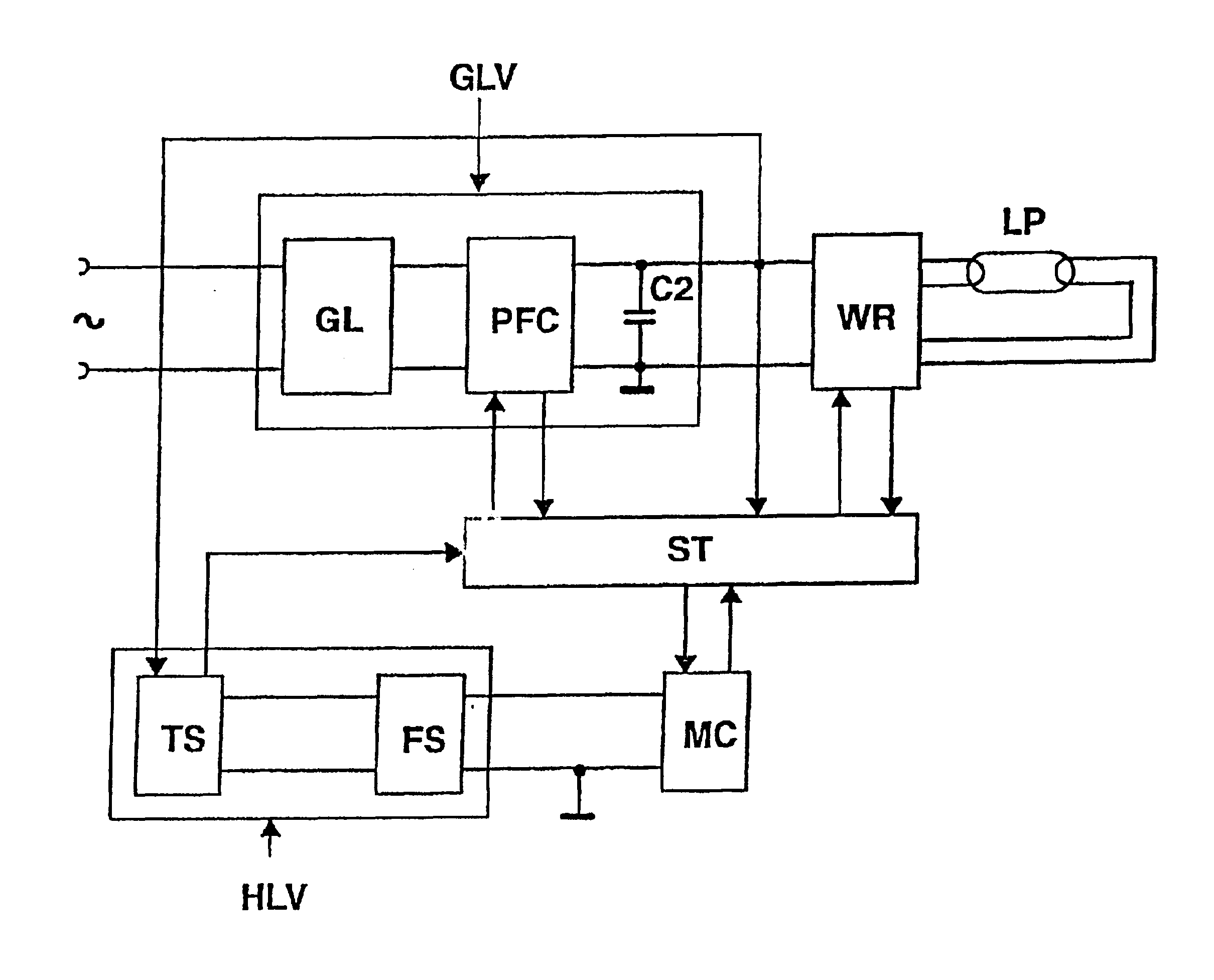
FIG. 1 shows a block diagram of the ballast according to the invention

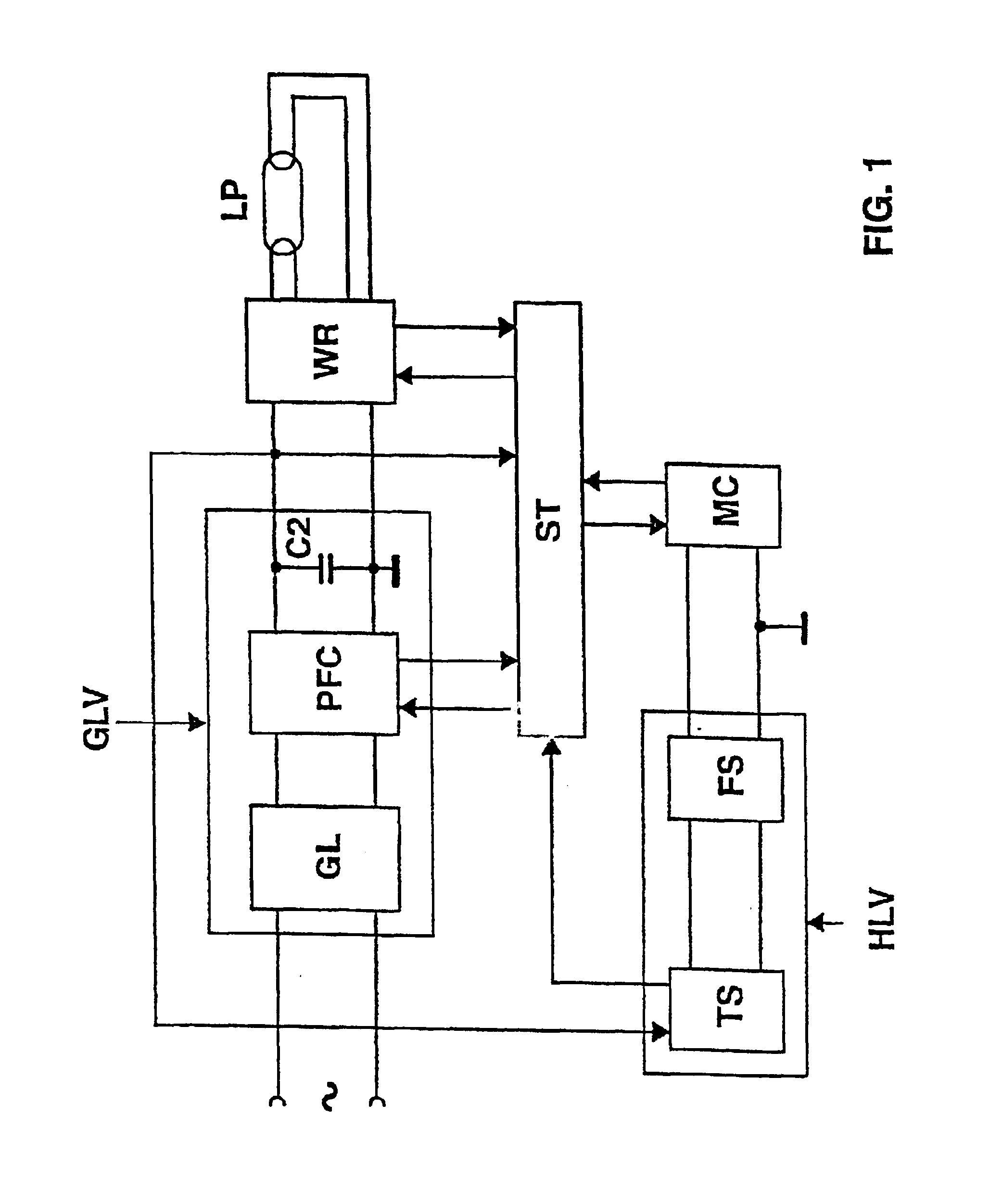
FIG. 2 shows a schematic representation of the step-down converter of the ballast depicted in figure

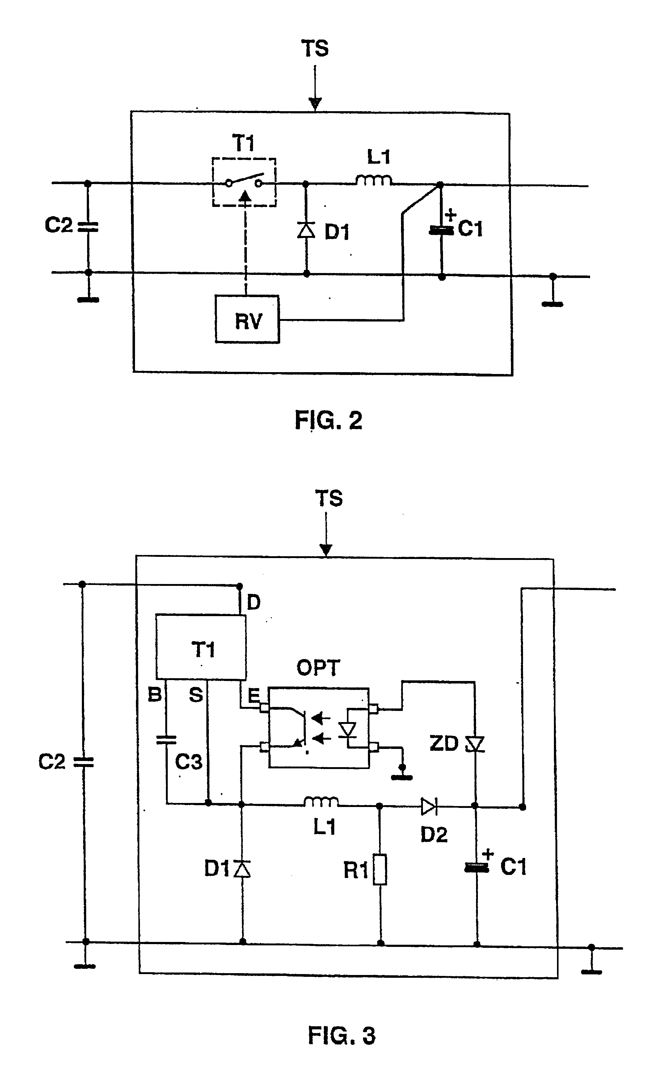
FIG. 3 shows details of the step-down converter of the ballast depicted in FIG. 1.

In FIG. 1, a preferred exemplary embodiment of the invention is represented schematically, in the form of a block diagram. The main component part of this ballast is an inverter WR, in particular a half-bridge inverter, for operating at least one low-pressure gas-discharge lamp LP, in particular a fluorescent lamp. The half-bridge inverter WR is fed by the DC voltage supply circuit GLV, which generates a DC voltage of approximately 400 V to 450 V from the AC line voltage. The DC voltage supply circuit GLV has for this purpose a module GL, which is connected to the line voltage terminals and comprises a radio-interference sup...


PUM


Abstract

The invention relates to a ballast for operating electric lamps, having an inverter (WR), a DC voltage supply circuit (GLV) for the inverter (WR), a load circuit, connected to the inverter (WR), for supplying voltage to one or more electric lamps (LP), a microcontroller (MC) for monitoring and controlling the operation of the ballast and a voltage supply device (HLV) for the microcontroller (MC). According to the invention, the voltage supply device (HLV) is designed as a DC-DC converter-in particular as a step-down converter-, which ensures a voltage supply to the microcontroller (MC) even in the standby mode of the ballast with the inverter (WR) deactivated. As a result, the power consumption in the standby mode can be reduced to less than 0.5 W.

Description

The invention relates to a ballast for operating electric lamps according to the preamble of patent claim 1.I. TECHNICAL FIELDThe invention relates in particular to a modern electronic ballast for operating electric lamps which has, in addition to an inverter and its control device, also a microcontroller for monitoring and controlling the functions of the ballast and the lamps operated on it. The microcontroller also makes bidirectional communication possible with a central control unit which is arranged outside the ballast and serves for the central closed-loop or open-loop control of a room lighting system, usually comprising a plurality of luminaires and consequently also a plurality of ballasts.II. PRIOR ARTThe European laid-open application EP 0 564 895 A1 describes an electronic ballast for the operation of low-pressure gas-discharge lamps. This ballast has an inverter, a DC voltage supply circuit for the inverter, a load circuit, connected to the inverter, for supplying volt...

Claims


Application Information

Patent Timeline
Patent Type & Authority Patents(United States)
IPC IPC(8): H05B41/282H05B41/28H05B41/26
CPCH05B41/2828H02M2001/0006Y02B20/186Y02B20/00H02M1/0006H05B41/26
Inventor HUBER, ANDREASNIEDERMAIER, MARTIN
Owner ABL IP HLDG
Why Eureka
Try Eureka