Ballast for operating electric lamps

a technology of electric lamps and ballasts, which is applied in the field of modernity, can solve the problems that the voltage supply to the control device of the inverter is unsuitable for this purpose, and achieve the effect of low power loss and low barrier-layer capacitan

Inactive Publication Date: 2002-08-15
ABL IP HLDG
View PDF0 Cites 15 Cited by
  • Summary
  • Abstract
  • Description
  • Claims
  • Application Information

AI Technical Summary

Benefits of technology

0006] The ballast according to the invention has an inverter, a DC voltage supply circuit for the inverter, a load circuit, connected to the inverter, for supplying voltage to one or more electric lamps, a microcontroller for monitoring and controlling the operation of the ballast or the lamps and a voltage supply device for the microcontroller. According to the invention, the voltage supply device of the microcontroller is designed as a DC-DC converter, the voltage input of which is connected to the voltage output of the DC voltage supply circuit of the inverter and the voltage output of which is connected to the supply voltage input of the microcontroller. The DC-DC converter makes it possible to generate the supply voltage for the microcontroller directly from the AC line voltage rectified by the DC voltage supply circuit, to be precise independently of the operating state of the inverter and the lamps. What is more, the electrical power consumption of the ballast in the standby mode can be lowered to approximately 0.5 W.
0007] The voltage output of the DC-DC converter is advantageously additionally connected also to the supply voltage input of the control device for the inverter switching means. The components of the DC-DC converter are advantageously dimensioned in such a way that an adequately high voltage for supplying both the microcontroller and the control device of the inverter is available at its voltage output. The DC-DC converter can therefore be additionally used also for supplying voltage to this control device. The DC-DC converter advantageously has a step-down converter or is designed as a step-down converter, because a low-volt DC voltage, as required for operating the microcontroller, can be generated with the aid of a step-down converter in a simple way and with relatively low power loss from the comparatively high output voltage of the DC voltage supply circuit. The voltage output of the step-down converter is advantageously formed by an electrolytic capacitor, in order to be able to make an adequately high supply current, of for example 5 mA, available for the control device of the inverter for a short time period, of for example 200 ms. The switching means of the step-down converter and the closed-loop control device for controlling its switching operations are advantageously designed as an integrated circuit. As a result, a space-saving arrangement of the step-down converter or the device for supplying voltage to the microcontroll

Problems solved by technology

The device disclosed in the laid-open application EP 0 564 895 A1 for supplyin

Method used


Image

  • Ballast for operating electric lamps
  • Ballast for operating electric lamps
  • Ballast for operating electric lamps

Examples


Embodiment Construction

[0008] The invention is explained in more detail below on the basis of a preferred exemplary embodiment. In the drawing:

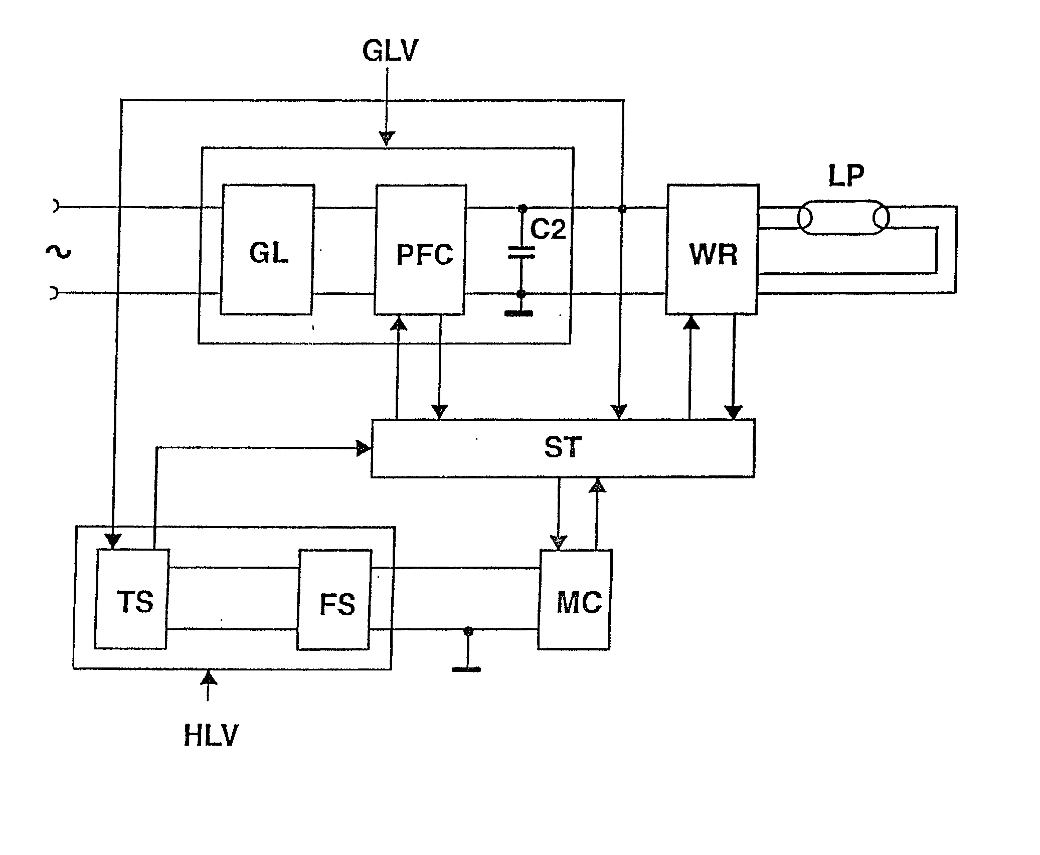
[0009] FIG. 1 shows a block diagram of the ballast according to the invention

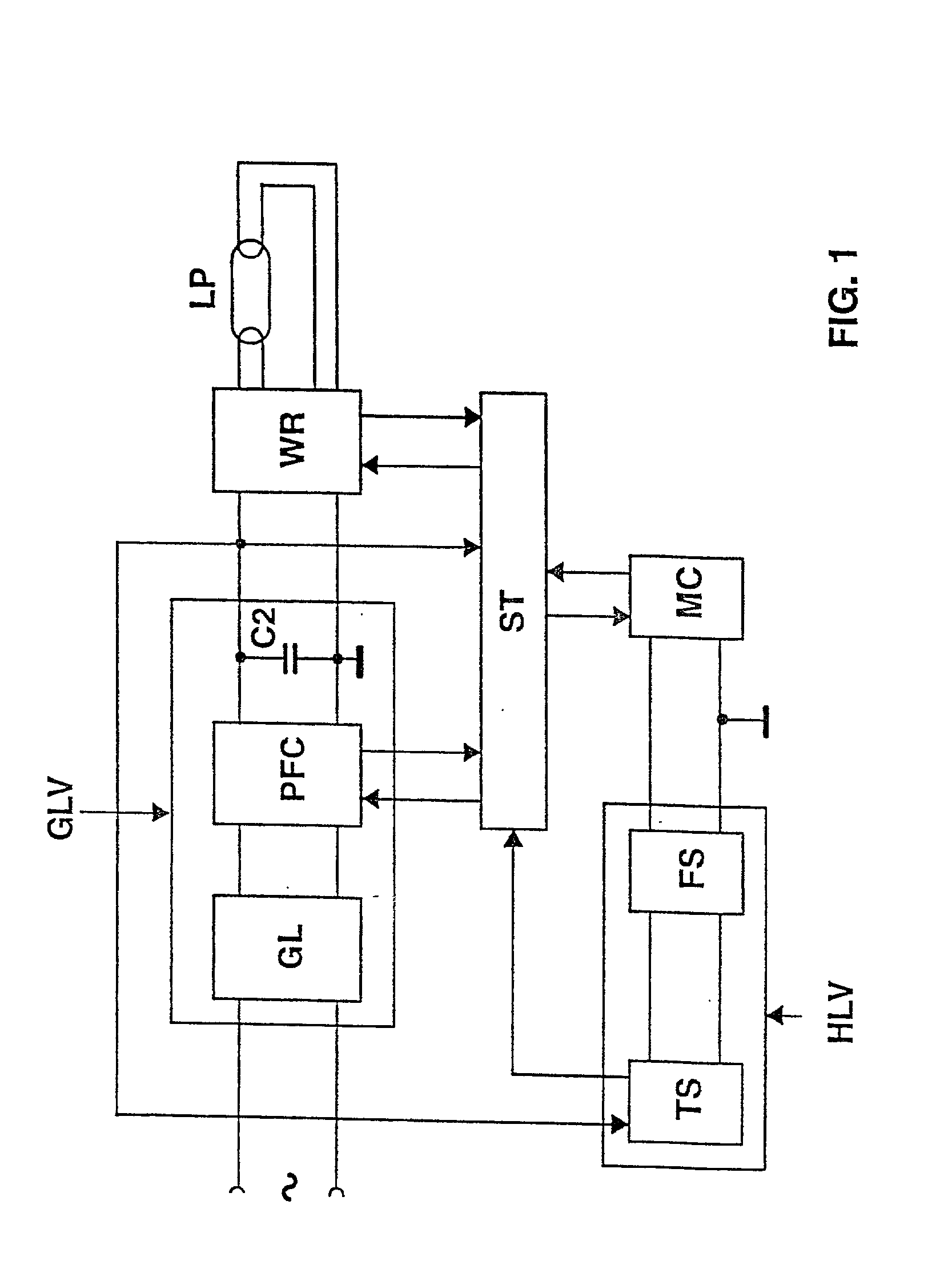
[0010] FIG. 2 shows a schematic representation of the step-down converter of the ballast depicted in figure

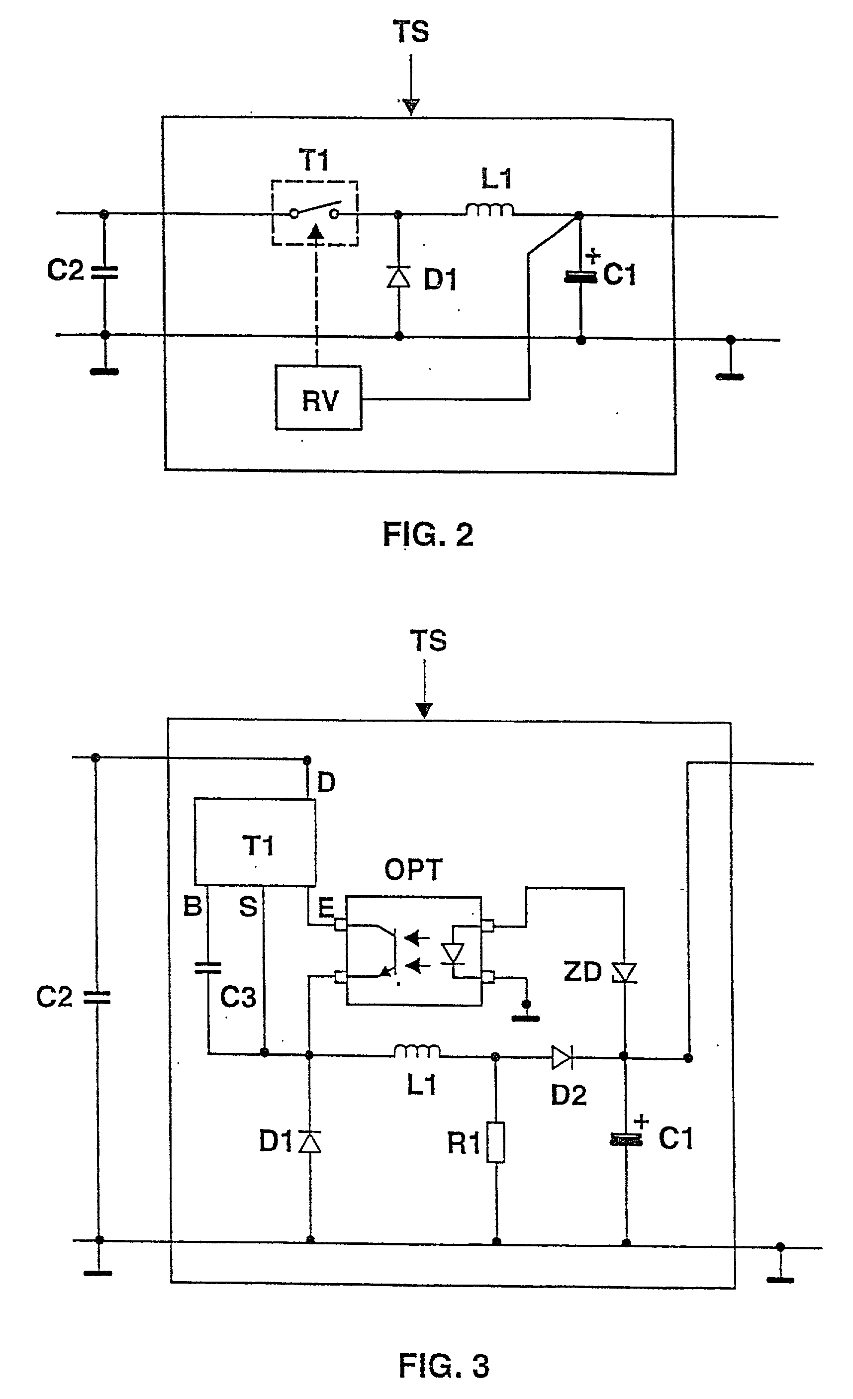
[0011] FIG. 3 shows details of the step-down converter of the ballast depicted in FIG. 1.

[0012] In FIG. 1, a preferred exemplary embodiment of the invention is represented schematically, in the form of a block diagram. The main component part of this ballast is an inverter WR, in particular a half-bridge inverter, for operating at least one low-pressure gas-discharge lamp LP, in particular a fluorescent lamp. The half-bridge inverter WR is fed by the DC voltage supply circuit GLV, which generates a DC voltage of approximately 400 V to 450 V from the AC line voltage. The DC voltage supply circuit GLV has for this purpose a module GL, which is connected to the line voltage terminals and...


PUM


Abstract

The invention relates to a ballast for operating electric lamps, having an inverter (WR), a DC voltage supply circuit (GLV) for the inverter (WR), a load circuit, connected to the inverter (WR), for supplying voltage to one or more electric lamps (LP), a microcontroller (MC) for monitoring and controlling the operation of the ballast and a voltage supply device (HLV) for the microcontroller (MC). According to the invention, the voltage supply device (HLV) is designed as a DC-DC converter-in particular as a step-down converter-, which ensures a voltage supply to the microcontroller (MC) even in the standby mode of the ballast with the inverter (WR) deactivated. As a result, the power consumption in the standby mode can be reduced to less than 0.5 W.

Description

[0001] The invention relates to a ballast for operating electric lamps according to the preamble of patent claim 1.I. TECHNICAL FIELD[0002] The invention relates in particular to a modern electronic ballast for operating electric lamps which has, in addition to an inverter and its control device, also a microcontroller for monitoring and controlling the functions of the ballast and the lamps operated on it. The microcontroller also makes bidirectional communication possible with a central control unit which is arranged outside the ballast and serves for the central closed-loop or open-loop control of a room lighting system, usually comprising a plurality of luminaires and consequently also a plurality of ballasts.II. PRIOR ART[0003] The European laid-open application EP 0 564 895 A1 describes an electronic ballast for the operation of low-pressure gas-discharge lamps. This ballast has an inverter, a DC voltage supply circuit for the inverter, a load circuit, connected to the inverte...

Claims


Application Information

Patent Timeline
IPC IPC(8): H05B41/282H05B41/26
CPCH02M2001/0006H05B41/2828Y02B20/186Y02B20/00H02M1/0006H05B41/26
Inventor HUBER, ANDREASNIEDERMAIER, MARTIN
Owner ABL IP HLDG
Why Eureka
Try Eureka