Feeder for a tube-filling machine

a tube-filling machine and feed tube technology, applied in the direction of packaging bottles, load-engaging elements, packaging, etc., can solve the problems of inability to increase without restriction, limit the amount of acceleration and deceleration the arrangement will tolerate, and it is not possible to find a simple, adaptable solution. , to achieve the effect of high capacity and easy adaptability

Inactive Publication Date: 2004-05-11
NORDEN MASCH AB
View PDF19 Cites 31 Cited by
  • Summary
  • Abstract
  • Description
  • Claims
  • Application Information

AI Technical Summary

Benefits of technology

The object of the invention is to develop the robot concept in tube-handling lines and to provide an arrangement for a robot which makes ...

Problems solved by technology

However, this cannot be increased without restriction since the necessary time for processing in different stations imposes a limit.
In addition, there are limits to what the arrangement will tolerate in terms of acceleration and deceleration.
A problem in this context is that it has not been possible to find a simple, adap...

Method used


Image

  • Feeder for a tube-filling machine
  • Feeder for a tube-filling machine
  • Feeder for a tube-filling machine

Examples


Embodiment Construction

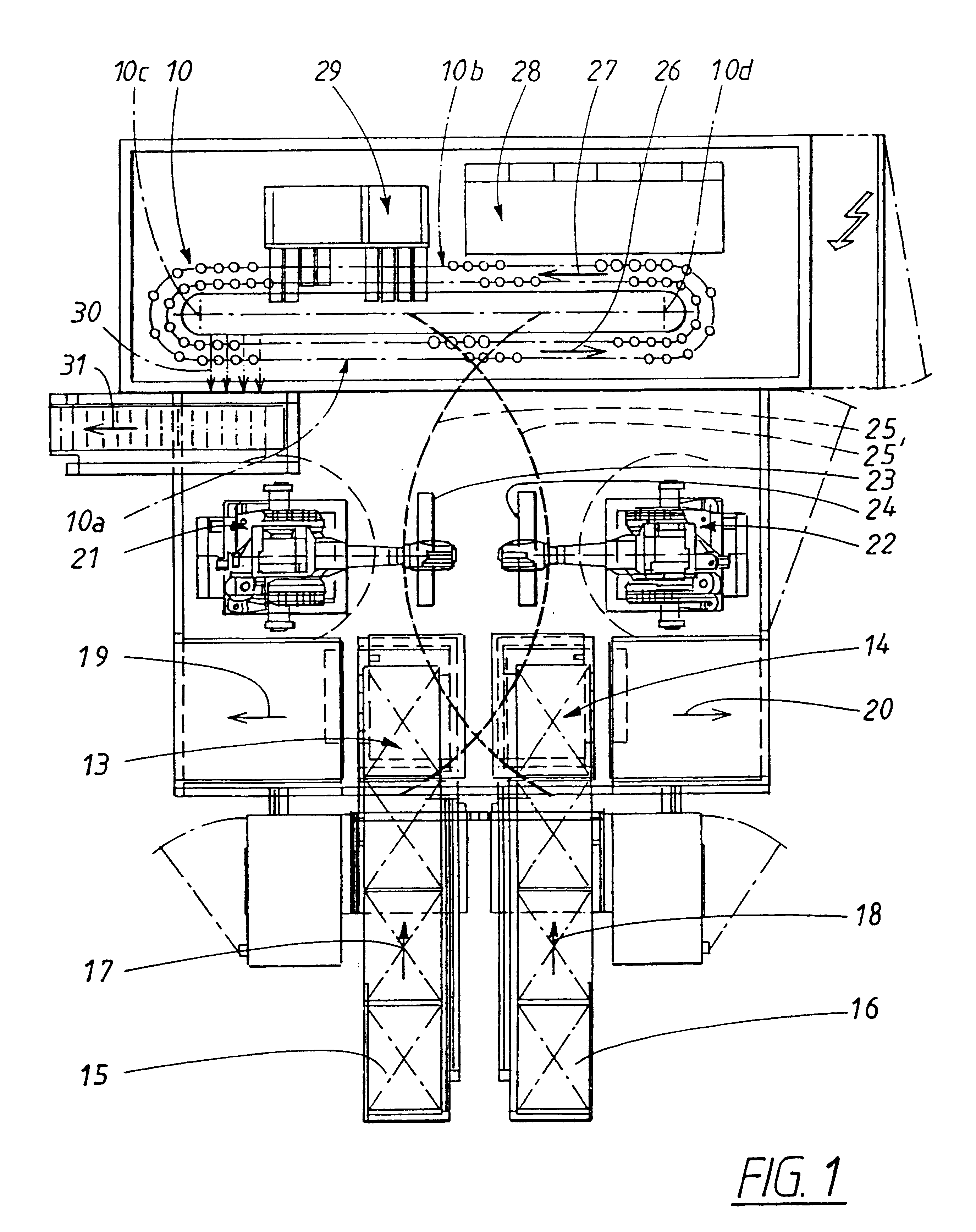
FIG. 1 shows a layout for a tube-handling machine with high production speed, up to 400-600 tubes per minute.

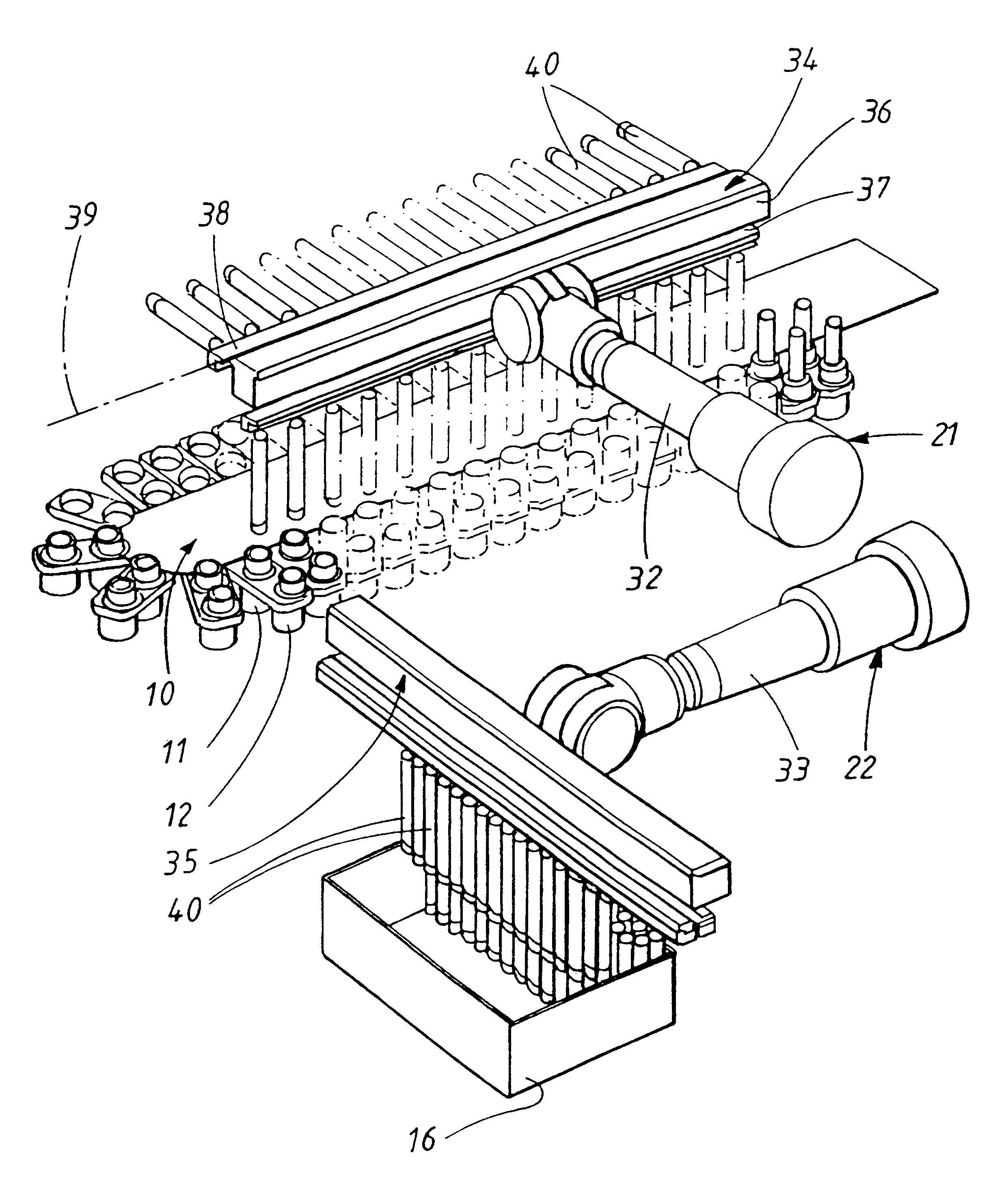
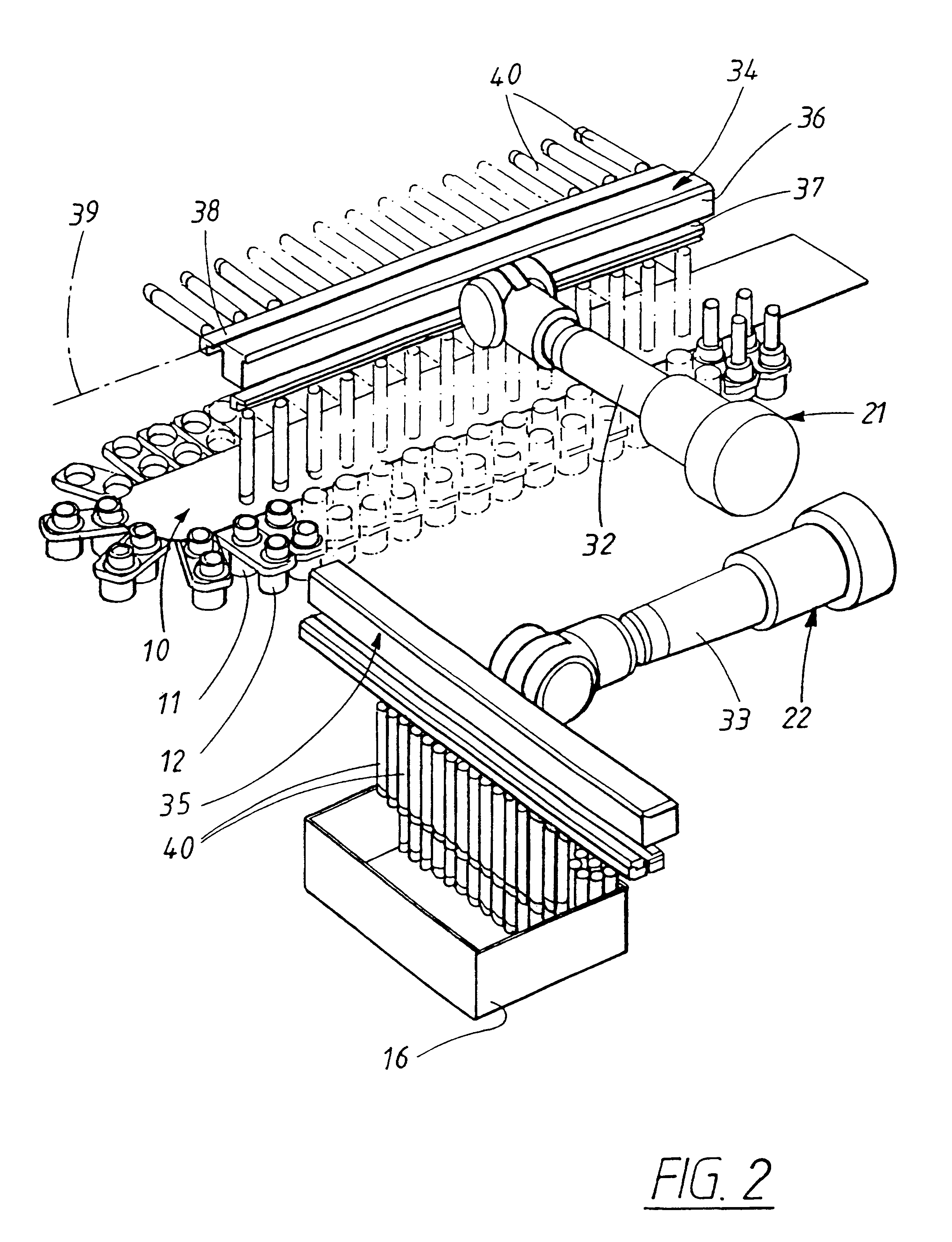
The machine has a continuous, intermittently operated conveyor 10 which is placed in the horizontal plane and which has two straight sections 10a, 10b and passes around deflector wheels 10c, 10d. Arranged along the conveyor there are double rows of tube holders 11, 12 (FIG. 2). Each pair of tube holders forms a unit, and in the embodiment shown each pair lies with its centre lines in a plane at right angles to the direction of transport, and with well-defined spacing (distance between the centre lines).

In the case in question, the intermittent operation is such that the conveyor advances in steps of a length of two spacings. Assuming that the machine is driven at 100 cycles per minute and that all the tube holders can be used, this gives a production capacity of 2.times.2.times.100=400 tubes per minute.

In the layout shown in FIG. 1, there are double collection stations 13, 14...


PUM

PropertyMeasurementUnit
Dimensionaaaaaaaaaa
Distanceaaaaaaaaaa

Abstract

The present invention relates to feeder assemblies, and more specifically, relates to feeder assemblies for a tube-filling machine. The present invention includes at least one robotic arm capable of moving tubes and tube holders between two locations. The robotic arm may also move the tubes and tube holders relative to one another in order that the distance between adjacent tubes is substantially equal to the holders which carry and house the tubes.

Description

The invention relates to machines / lines which, starting with empty packaging tubes, process these in the machine, including filling and sealing them, and output the tubes from the machine with high productivity / capacity.More precisely, the invention relates to a feeder intended to constitute a principal component in such a high-production machine.PRIOR ARTA number of different concepts have been proposed to increase the number of tubes produced per unit of time in a tube-filling line.In practice, intermittently operating lines have for many years formed the basis for tube handling. Such lines are operationally reliable and can, within certain limits, be converted relatively easily to the actual requirements regarding production volumes, type of sealing, tube dimension, etc.An advantageous type of intermittently operating machine is based on the principle of the continuous conveyor with two straight sections. Stations for processing the tubes are arranged along one straight section, ...

Claims


Application Information

Patent Timeline
IPC IPC(8): B65B3/04B65B43/42B65B43/46B65B3/16B65B43/44B65B35/36B65B43/52
CPCB65B3/16B65B43/46
Inventor LINNER, HANS
Owner NORDEN MASCH AB
Why Eureka
Try Eureka