Door track for an elevator door system

a door track and elevator technology, applied in the field of elevator doors, can solve the problems of degrading the door rolling performance, affecting the horizontal stiffness, and not always satisfactory alignment,

Inactive Publication Date: 2004-05-18
INVENTIO AG
View PDF5 Cites 5 Cited by
  • Summary
  • Abstract
  • Description
  • Claims
  • Application Information

AI Technical Summary

Benefits of technology

An advantage of the inventive elevator door is that field assembly time is reduced because the fast door portion does not require the mounting of another full-length header track for the fast door portion. Factory assembly of the coupling track to the back of the slow door hanger panel replaces the field work that would have been required to install this other full length track. Field adjustment of the door portions is reduced because of the positional coupling provided by the coupling track and the header track. Time required to replace an elevator door is also reduced because the door portions may be removed without the need to disassemble the header track and the coupling track.
Furthermore, the aluminum extended door track fits securely on the formed metal header and is easily assembled and / or removed therefrom. The spring clips maintain the original installation position. The aluminum material of the door track is a durable surface for a polyurethane roller. Finally, manufacture by the extrusion process provides a higher quality level than a roll formed track or a mechanical brake formed track and header.
The door track is mounted on the rail of the header track via an S-shaped spring clip having a retaining assembly arranged for retaining the spring clip onto the rail and for retaining the door track onto the spring clip. The retaining assembly includes a first protrusion or barb for engaging an indentation or notch in the header track for retaining the spring clip onto the header track. The retaining assembly also includes a second protrusion for engaging a profile on the door track for holding the door track onto the spring clip. The door track also has a profile to facilitate rolling of the rollers.

Problems solved by technology

Alignment is not always satisfactory and affects horizontal stiffness, thereby allowing deflection and degrading the door rolling performance.

Method used


Image

  • Door track for an elevator door system
  • Door track for an elevator door system
  • Door track for an elevator door system

Examples


Embodiment Construction

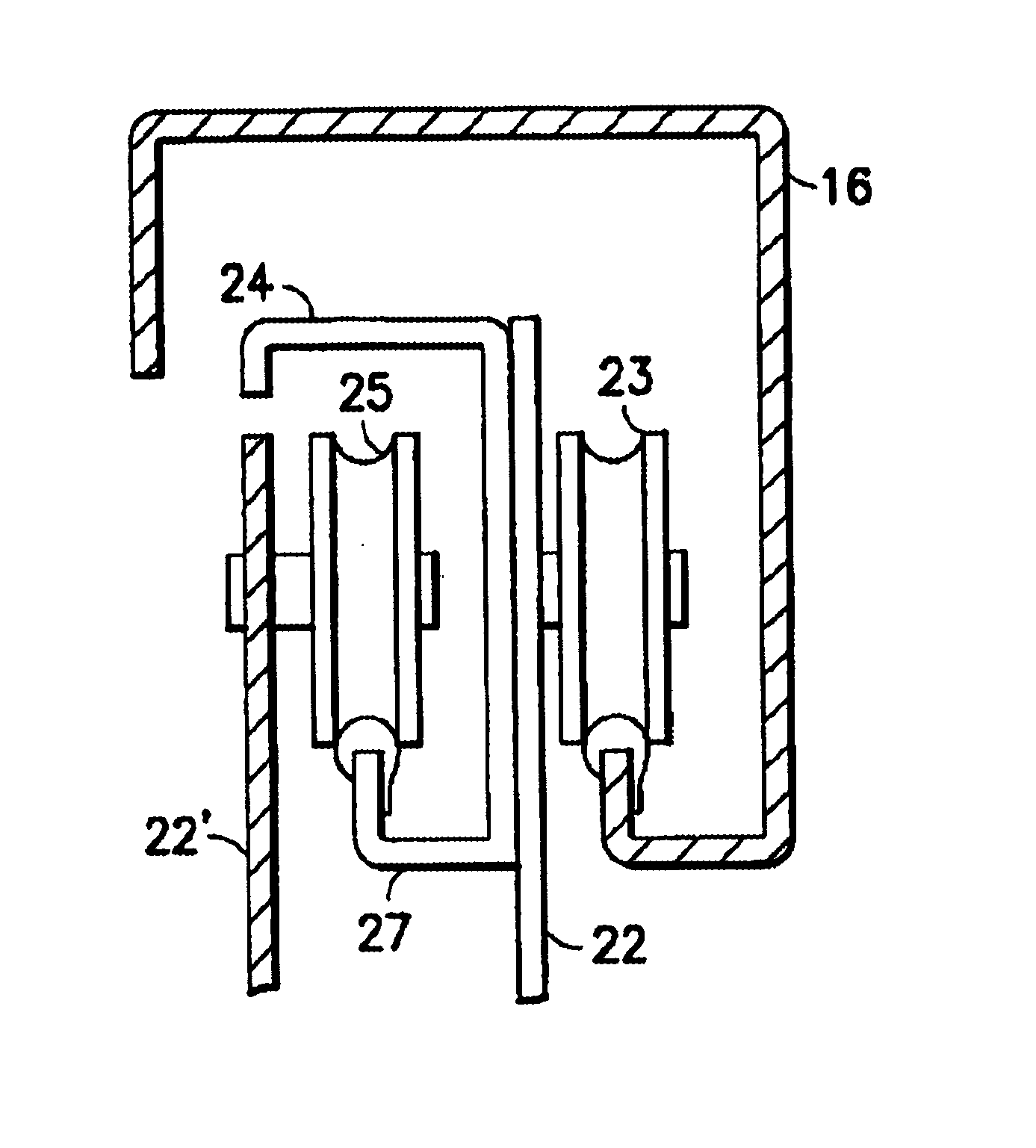
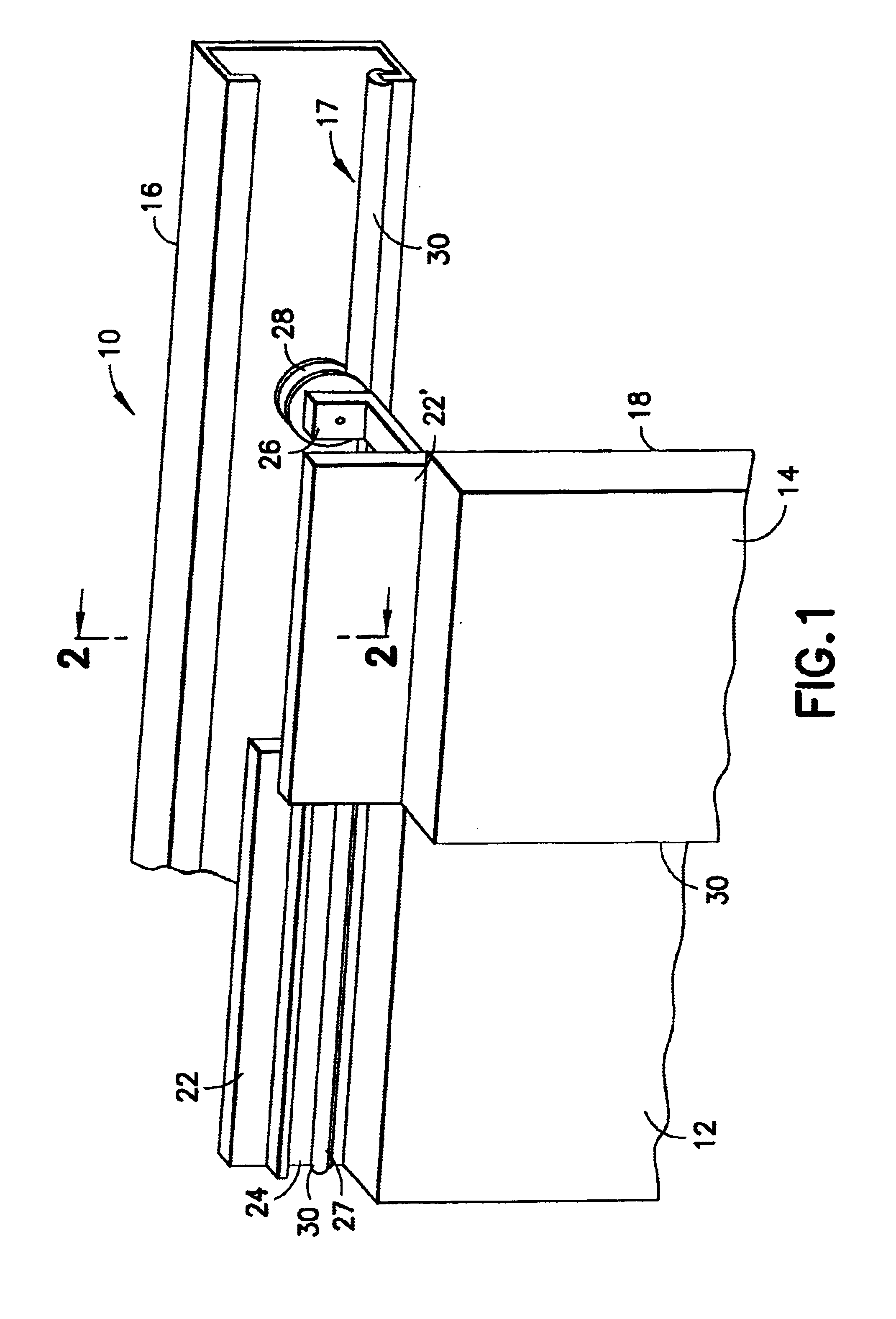
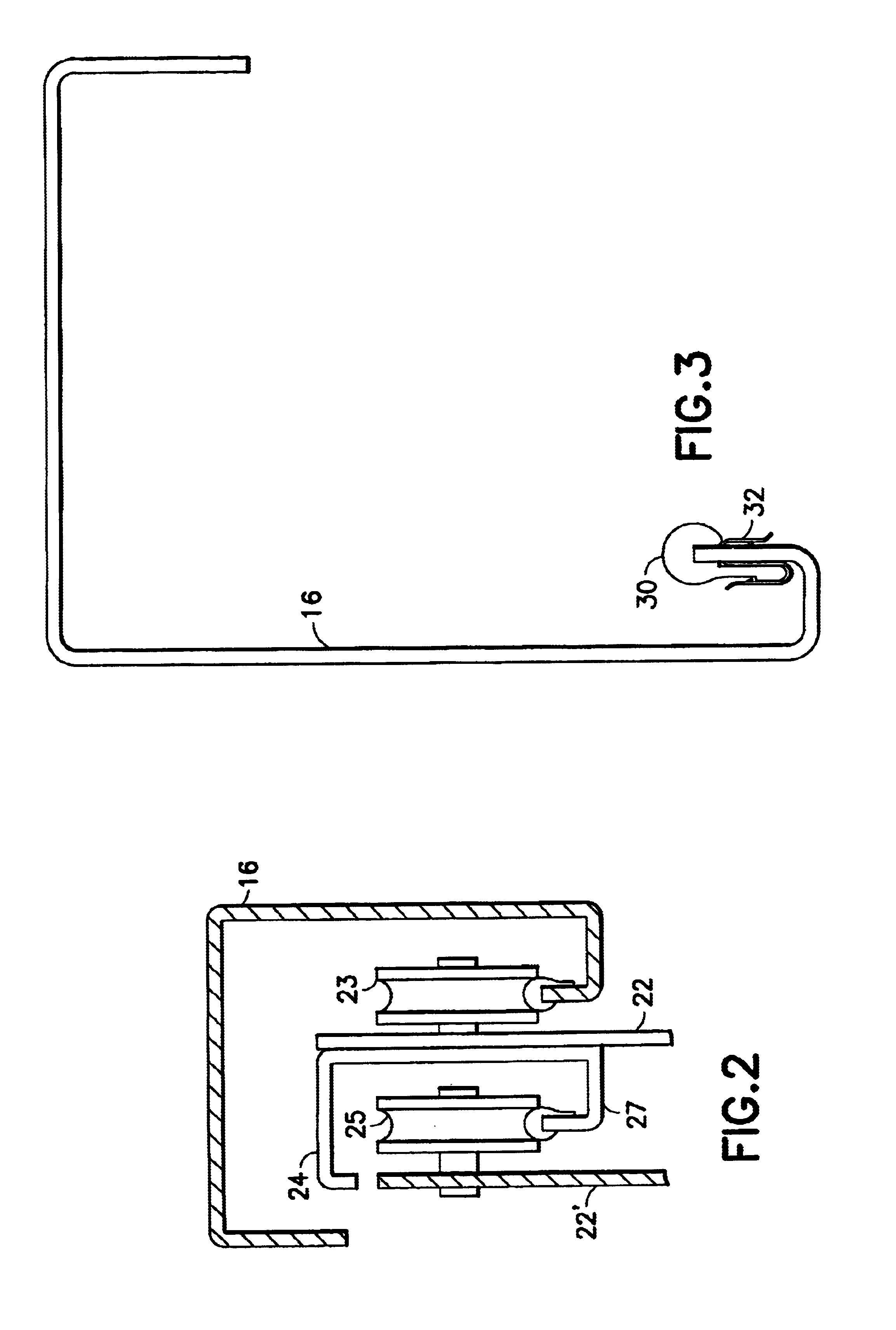
Referring now to the drawings, FIGS. 1 and 2 diagrammatically illustrate a two-speed elevator door system 10 of an embodiment of the present invention. The elevator door system 10 includes a two-part elevator door comprising a slow door portion 12 and a fast door portion 14 of substantially equal widths. The fast door portion 14 is configured to travel across and cover a portion (e.g., one-half) of the entrance opening to the elevator cab while the slow door portion 12 is configured to travel across and cover the remaining portion (e.g., the remaining one-half) of the elevator cab entrance opening. The fast and slow door portions 12, 14 are kinematically linked (by, for example, a conventional three-member linkage mechanism) and driven such that the fast door portion 14 traverses at a speed greater than that of the slow door portion 12.

Each door portion 12, 14 has a leading edge and a trailing edge. As defined herein, the leading edge of a door portion is that edge of the door porti...


PUM


Abstract

An elevator door system for an entrance opening to an elevator cab. The system includes a two-part door having an open position and a closed position. The two-part door includes a first door portion for traversing across and covering a portion of the entrance opening as the two-part door moves between the open position and the closed position of the two-part door. The two-part door also includes a second door portion for traversing across and covering another portion of the entrance opening as the two-part door moves between the open position and the closed position of the two-part door. A header track includes a rail with a door track for guiding movement of the first and the second door portions. The door track is held onto the rail of the header track via an S-shaped spring clip.

Description

1. Field of the InventionThe present invention relates to elevator doors and, more particularly, to an elevator door system having a header track with a door track mounted on the header track via spring clips for guiding elevator doors.2. Description of the Related ArtTypical elevators have a two-part door for opening and closing the entrance to the elevator cab. The two-part door includes a "fast" door portion and a "slow" door portion of equal widths. The "fast" door portion, located at the leading edge of the two-leaf door, traverses the entire width of the elevator entrance while the "slow" door portion traverses only about half the width of the elevator opening. Since the "fast" door portion must travel a greater distance, the "fast" door is required to move at a speed greater than that of the "slow" door so that the "fast" door and the "slow" door reach the open and closed positions at the same time.Prior art elevators utilize two separate header tracks: one for guiding the fa...

Claims


Application Information

Patent Timeline
Patent Type & Authority Patents(United States)
IPC IPC(8): E05D15/06
CPCE05D15/0652E05Y2201/684Y10T16/373E05Y2800/67E05Y2900/104E05Y2800/205B66B13/301
Inventor MILLER, MICHAEL G.
Owner INVENTIO AG
Why Eureka
Try Eureka