Process for high shear gas-liquid reactions

a gas-liquid reaction and high shear technology, applied in the field of material processing, can solve the problems of affecting the overall efficiency of the process, unable to provide adequate interfacial contact area between liquid and gas, and unfavorable large residence tim

Inactive Publication Date: 2004-06-01
323 TRUST
View PDF111 Cites 131 Cited by
  • Summary
  • Abstract
  • Description
  • Claims
  • Application Information

AI Technical Summary

Problems solved by technology

However, this gas / liquid reaction method provides a relatively small gas / liquid contact area and is prone to considerable back-mixing (mixing in the longitudinal, axial or general flow direction) of the gas component thus providing an undesirably large residence time distribution (RTD), impairing the overall efficiency of the process.
Sparging gasses through liquids for reacting the gasses with the liquids is also known in the prior art, but also fails to provide adequate interfacial contact area between the liquid and gas.

Method used


Image

  • Process for high shear gas-liquid reactions
  • Process for high shear gas-liquid reactions
  • Process for high shear gas-liquid reactions

Examples


Embodiment Construction

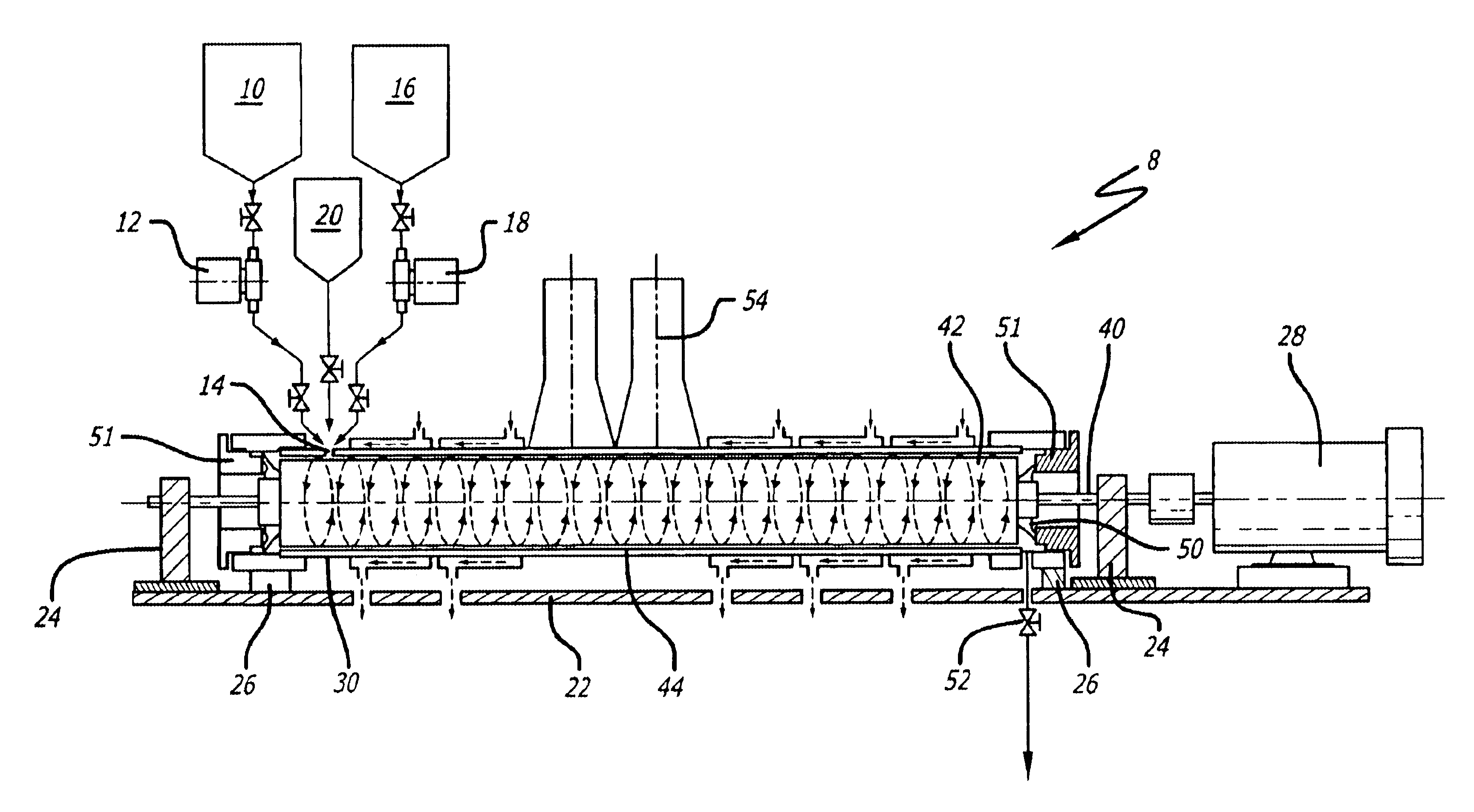
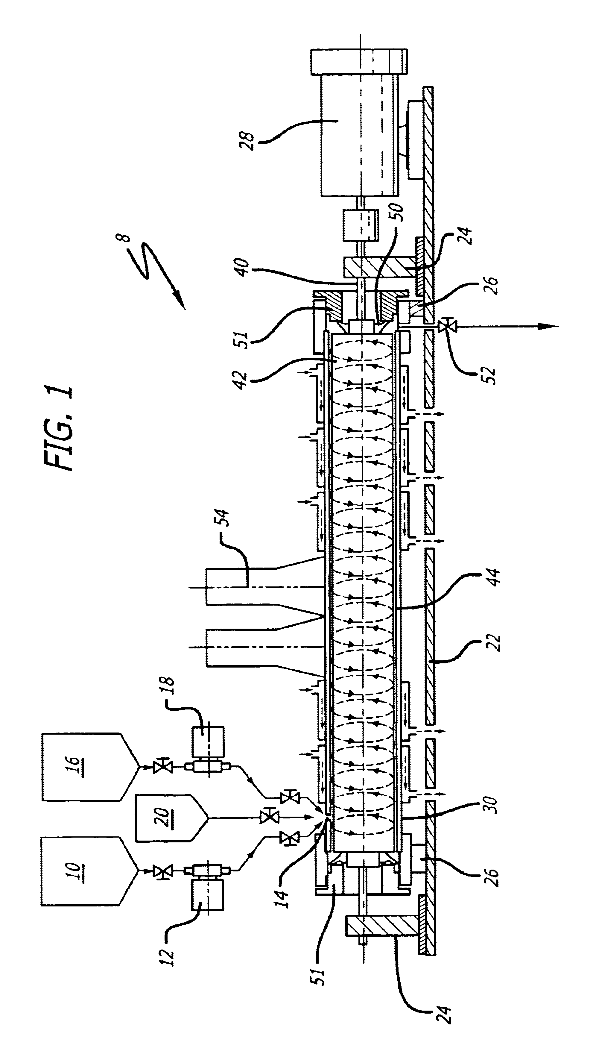
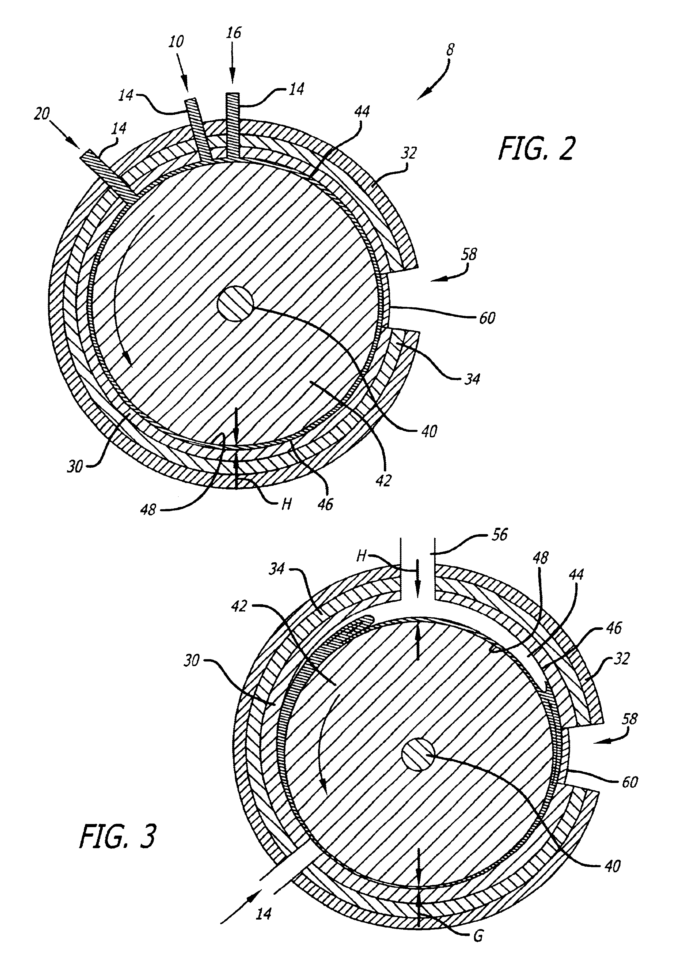
A reactor 8 is illustrated by FIGS. 1-4, and described in greater detail in U.S. patent Ser. No. 09 / 802,037 entitled "Method and Apparatus for Materials Processing", filed Mar. 7, 2001 and U.S. Pat. No. 5,538,191 entitled "Methods and Apparatus for High-Shear Material Treatment" both by the applicant of the present invention and both of which are hereby incorporated by reference in their entirety into the present disclosure. An annular cross section processing chamber 44 having an annular gap is formed between an outer cylindrical member or cylindrical tube 30 comprising a stator and a cylindrical rotor or inner cylindrical member 42. Liquid and gas enter the processing chamber 44 through inlets 14. The cylindrical members 30, 42 rotate relative to each other producing a shear force on the liquid, gas and any other reactants as they are pumped through the processing chamber and out an outlet 52 at the downstream end of the processing chamber 44.

Turning to FIGS. 1 and 2 in particular...


PUM

PropertyMeasurementUnit
diametersaaaaaaaaaa
diametersaaaaaaaaaa
relative speedaaaaaaaaaa

Abstract

A reactor produces a gas-in-liquid emulsion for providing increased interfacial contact area between the liquid and the gas for improved reaction of the gas with the liquid, or more rapid solution or reaction of a difficulty soluble or immiscible gas in or with a liquid. The reactor is suitable for a continuous or batch type process. Rotor and stator cylindrical members are mounted for rotation relative to one another and have opposing surfaces spaced to form an annular processing passage. The gap distance between the opposing surfaces and the relative rotation rate of the cylindrical members are such as to form a gas-in-liquid emulsion of the gas in the liquid. The liquid and gas pass through the processing passage, changing into the gas-in-liquid emulsion.

Description

1. Field of the InventionThe present invention relates to materials processing involving a chemical and / or a physical action(s) or reaction(s) of a component or between components. More specifically, the present invention produces a gas-in-liquid emulsion in a reactor to continuously process relatively large quantities of materials.2. General Background and State of the ArtApparatus for materials processing consisting of coaxial cylinders that are rotated relative to one another about a common axis, the materials to be processed being fed into the annular space between the cylinders, are known. For example, U.S. Pat. No. 5,370,999, issued Dec. 6, 1994 to Colorado State University Research Foundation discloses processes for the high shear processing of a fibrous biomass by injecting a slurry thereof into a turbulent Couette flow created in a "high-frequency rotor-stator device", this device having an annular chamber containing a fixed stator equipped with a coaxial toothed ring coope...

Claims


Application Information

Patent Timeline
Patent Type & Authority Patents(United States)
IPC IPC(8): B01J19/08B01J19/10B01J19/12B01J19/18B01F13/00B01F15/00B29B7/90B29B7/34B29B7/40B29B7/00B29C47/50B29C47/38C08K3/00F28D11/02F28D11/00H05K3/02B01F13/10B01F7/00C02F1/36C02F1/34C02F1/30C02F1/32H05K1/03B01F27/74B29C48/38
CPCB01F7/008B01F7/12B01F13/0001B01F15/00714B01J19/082B01J19/10B01J19/122B01J19/125B01J19/126B01J19/127B01J19/18B01J19/1887B29B7/401B29B7/90B29C47/50C08K3/0008F28D11/02B01F7/005B01F15/00844B01F15/00909B01F15/06B01F2013/1086B01F2013/1091B01J2208/00B01J2219/00094B01J2219/00141B01J2219/00146B01J2219/00164B01J2219/00166B01J2219/00168B01J2219/0888B01J2219/1227B01J2219/182B01J2219/1943B22F2998/00B29C47/0009B29K2021/00B29K2105/16B29K2503/04C02F1/30C02F1/302C02F1/32C02F1/36C22C32/0094C08K3/01B29C48/03B29C48/38B01F27/116B01F27/272B01F27/74B01F33/05B01F33/8362B01F33/83613B01F35/4122B01F35/512B01F35/54B01F35/90
Inventor HOLL, RICHARD A.
Owner 323 TRUST
Why Eureka
Try Eureka