
Reaction apparatus, reaction system, and liquid phase hydrogenation reaction method

A technology of a reaction device and a liquid phase, which is applied in the field of hydrocarbon oil hydrogenation, can solve problems such as the adverse effect of the reaction rate of the hydrotreating process, and achieve the effect of good hydrogenation reaction and improved efficiency.

Active Publication Date: 2017-10-13
湖南长科诚享石化科技有限公司
View PDF6 Cites 12 Cited by
  • Summary
  • Abstract
  • Description
  • Claims
  • Application Information

AI Technical Summary

Problems solved by technology

The traditional trickle bed hydrogenation process is a gas-liquid-solid three-phase hydrogenation process, and a large amount of circulating hydrogen needs to be maintained in the reaction system; and, during the hydrogenation reaction, hydrogen needs to enter the liquid phase from the gas phase, and then be combined with the reactants Adsorbed on the surface of the catalyst to react under the action of the active center of the catalyst, this mass transfer process will undoubtedly have an adverse effect on the reaction rate of the hydrotreating process

Method used


Image

  • Reaction apparatus, reaction system, and liquid phase hydrogenation reaction method
  • Reaction apparatus, reaction system, and liquid phase hydrogenation reaction method
  • Reaction apparatus, reaction system, and liquid phase hydrogenation reaction method

Examples


Embodiment 1

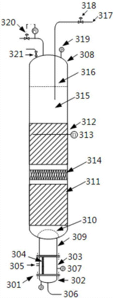
[0120] This example is in Figure 4 shown in the reaction system, wherein, using image 3 The reaction setup is shown.

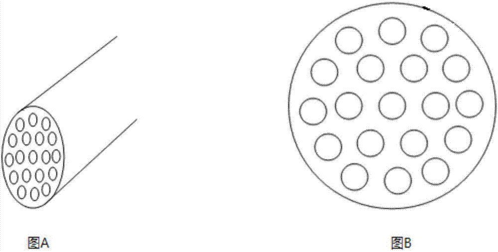
[0121] The component in the mixer is a pipeline with a porous wall (commercially purchased from Beijing Zhongtianyuan Environmental Engineering Co., Ltd., the cross-section of the pipeline is as follows: figure 1 As shown, there are 19 liquid channels evenly distributed on the pipeline, the inner diameter of each liquid channel is 3.3mm, the average pore diameter of the pores on the tube wall is 50nm, and the proportion of pores with a pore diameter in the range of 50-55nm to the total pores is 98%, porosity 20%), the pipe is used in conjunction with a shell, the space formed by the outer wall of the pipe and the inner wall of the shell is a raw material channel, and the channel on the pipe body is a mixing channel. The ratio between the inner diameter of the raw material mixture outlet on the mixer, the inner diameter of the reaction raw material inlet on...

Embodiment 2

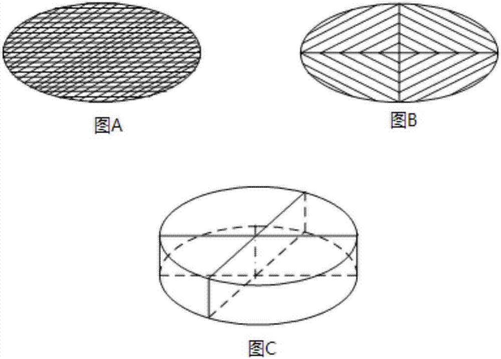
[0130] The hydrogenation reaction is carried out in the same manner as in Example 1, except that instead of a porous screen, a rib-type separation member is set between the catalyst beds, wherein the number of ribs is two, and two The ribs are arranged in a criss-cross pattern, which divides the radial section of the ribs into four pieces with equal areas. The property parameters of the resulting stripped product stream are listed in Table 1.

Embodiment 3

[0132] Adopt the method identical with embodiment 1 to carry out hydrogenation reaction, difference is, the separating member that is provided with between catalyst bed is porous screen cloth (same as embodiment 1) and rib plate type separating member (same embodiment 2), Wherein, based on the flow direction of the reaction materials, the rib-type partition member is located upstream of the porous screen. The property parameters of the gaseous product stream obtained are listed in Table 1.


PUM

PropertyMeasurementUnit
pore sizeaaaaaaaaaa
pore sizeaaaaaaaaaa
pore sizeaaaaaaaaaa

Abstract

The present invention discloses a gas-liquid reaction apparatus, which comprises a reactor and a mixer, wherein the internal space of the reactor is provided with n catalytic reaction zones for filling a catalyst, n is an integer of more than 2, the m-th catalytic reaction zone and the (m+1)-th catalytic reaction zone are connected through a separation member, m is any integer selected from an interval [1, n-1], and the separation member is used for dividing the radial cross section of the catalytic reaction zone of the separation member into a plurality of sub-zones, and making the material output from the m-th catalytic reaction zone enter the (m+1)-th catalytic reaction zone through the plurality of the sub-zones. The invention further discloses a liquid phase hydrogenation reaction system using the reaction apparatus and a liquid phase hydrogenation treatment method. According to the present invention, with the application of the reaction apparatus to perform liquid phase hydrogenation on hydrocarbon oil, the hydrocarbon oil can be subjected to liquid phase hydrogenation without application of the circulating oil and the diluent, and the efficiency of the hydrogenation reaction can be effectively improved so as to achieve the good hydrogenation reaction effect.

Description

technical field [0001] The present invention relates to the technical field of hydrocarbon oil hydrogenation, in particular, the present invention relates to a reaction device and a reaction system suitable for a liquid phase hydrogenation process, and the present invention also relates to a liquid phase hydrogenation reaction method using the reaction system. Background technique [0002] Refining and processing technologies mainly include catalytic cracking, hydrogenation and delayed coking. Among them, oil hydrogenation technology is one of the most commonly used technologies in oil refining technology. As the trend of heavy and low-quality crude oil intensifies, and countries around the world have higher and higher requirements for the cleanliness of oil products, hydrogenation units account for an increasing proportion. [0003] At present, the refining hydrogenation process mainly includes fixed bed hydrogenation process, ebullating bed hydrogenation process and suspe...

Claims


Application Information

Patent Timeline
Patent Type & Authority Applications(China)
IPC IPC(8): B01J8/04C10G67/02
CPCB01J8/0292B01J8/0453B01J8/0492B01J8/0496B01J2208/00044B01J2208/00398B01J2208/00849B01J2208/00884C10G67/02C10G2300/202C10G2300/205
Inventor 高伟军佘喜春刘凯中
Owner 湖南长科诚享石化科技有限公司
Learn More