
Self-suction type inner circulation overweight field gas-liquid reactor

A gas-liquid reactor and internal circulation technology, which is applied in chemical methods, chemical instruments and methods, and chemical/physical processes for reacting liquids and gaseous media. High processing technology requirements and other issues, to achieve the effect of inhibiting the accumulation of bubbles, eliminating the macroscopic vortex, and increasing the reaction rate

Inactive Publication Date: 2008-10-29
JIANGNAN UNIV +1
View PDF0 Cites 12 Cited by
  • Summary
  • Abstract
  • Description
  • Claims
  • Application Information

AI Technical Summary

Problems solved by technology

However, the reactor has high requirements on the equipment processing technology, and there are many places for rotating seals, and the seals are replaced frequently, which has become a key point in the supergravity technology.

Method used


Image

  • Self-suction type inner circulation overweight field gas-liquid reactor
  • Self-suction type inner circulation overweight field gas-liquid reactor
  • Self-suction type inner circulation overweight field gas-liquid reactor

Examples


Embodiment Construction

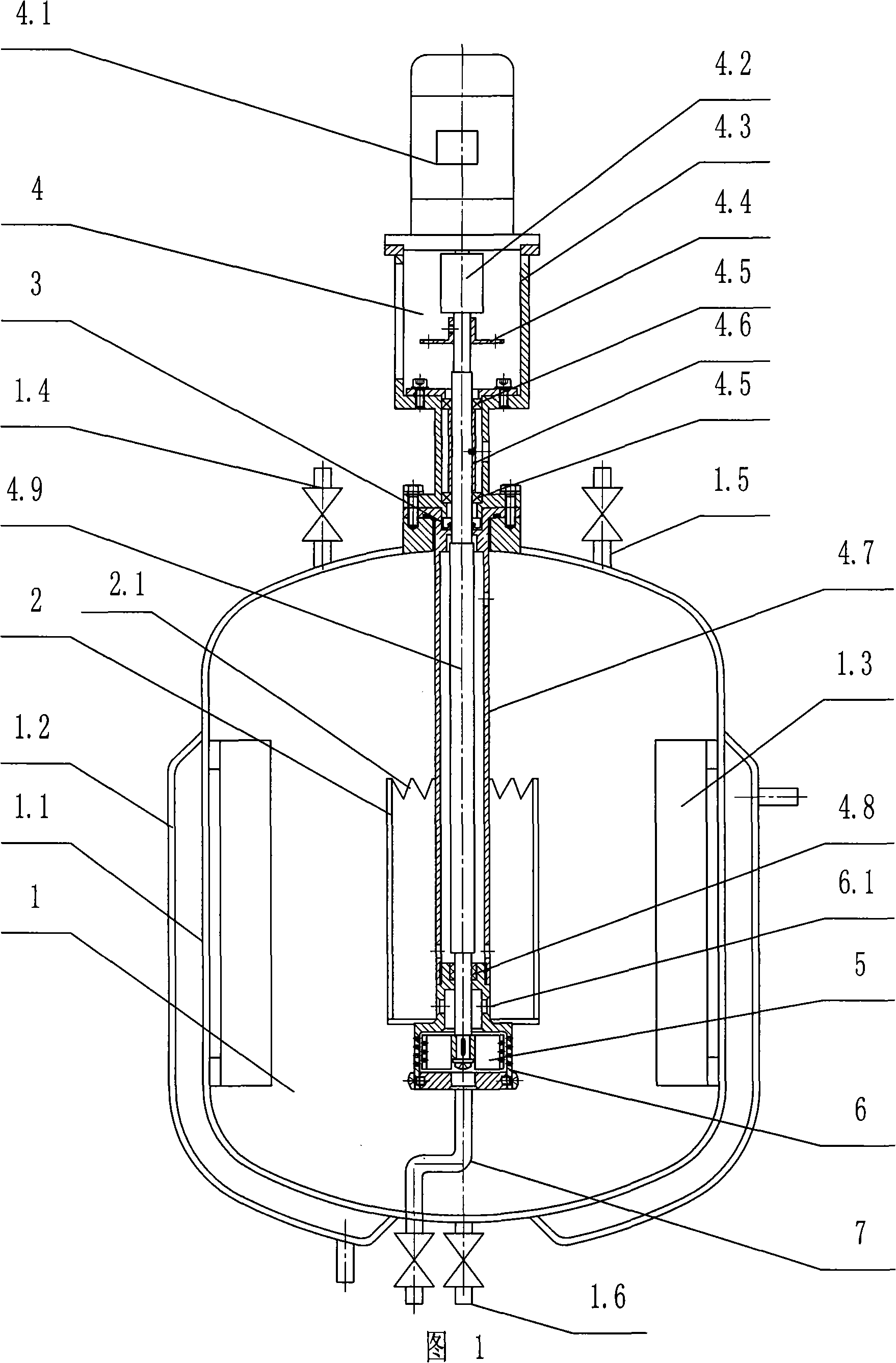
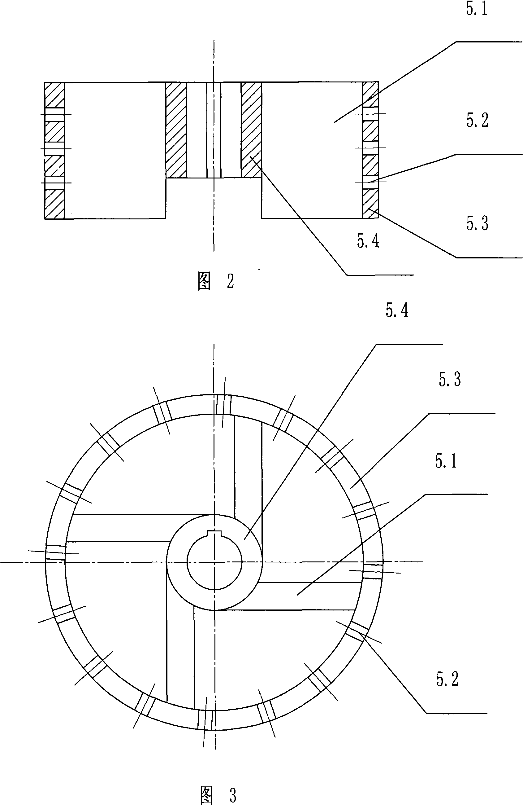
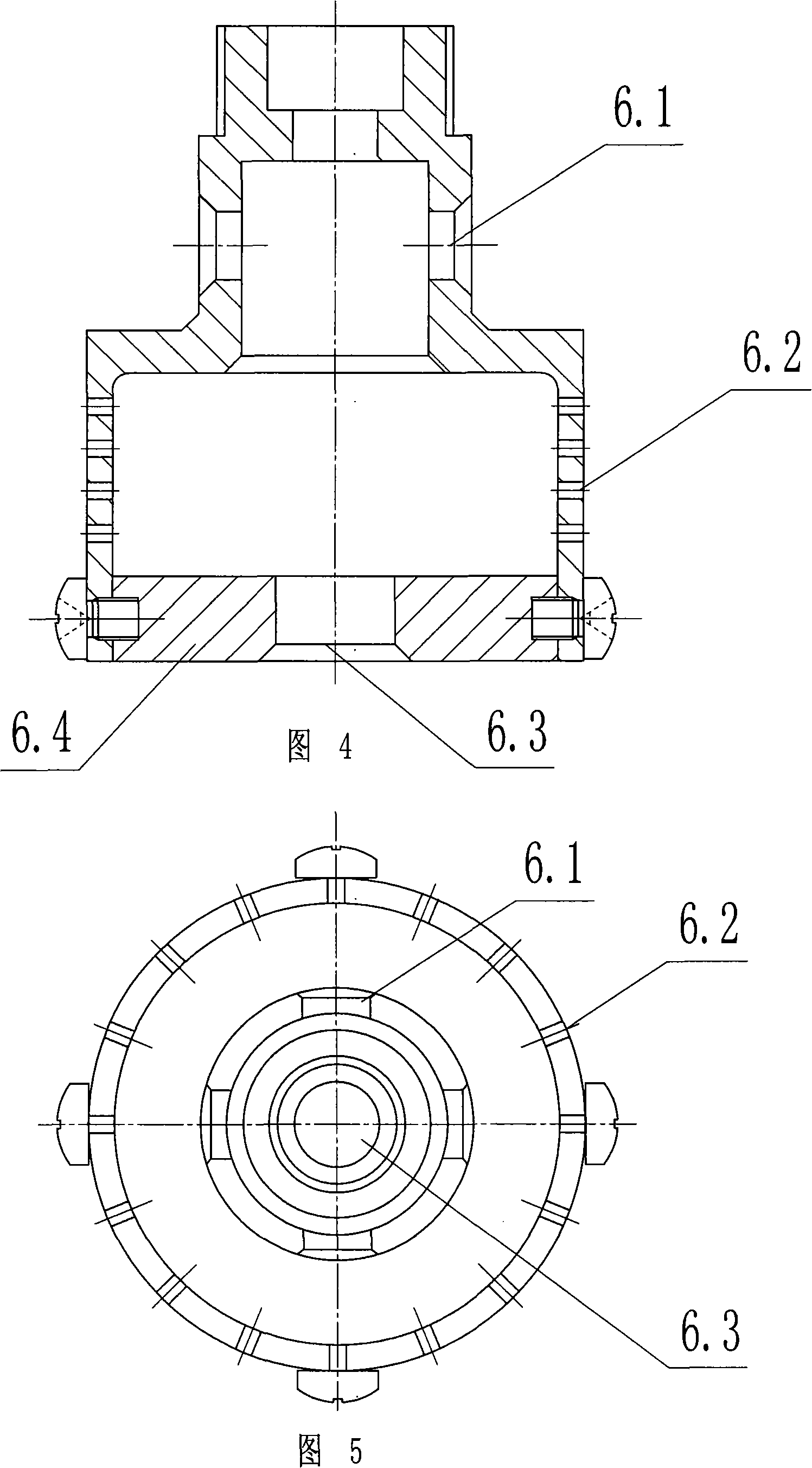
[0017] Figure 1 shows a schematic structural diagram of a self-priming internal circulation super-heavy field gas-liquid reactor, which mainly consists of a reactor vessel main body 1, a power rotor 5, a stator 6, a guide tube 2, a gas inlet pipe 7, a driving mechanism 4 and a sealing mechanism 3, characterized in that: the main body 1 is connected with the driving mechanism 4 and the sealing mechanism 3, the power rotor 5 is connected with the shaft 4.9 of the driving mechanism 4, and installed in the stator 6, and the stator 6 is connected with the connecting pipe 4.7 of the driving mechanism 4, The guide tube 2 is connected with the stator 6 , and the gas inlet pipe 7 is arranged at the lower part of the stator 6 .

[0018] The container body 1 includes an inner cylinder 1.1, a jacket 1.2 located outside the inner cylinder 1.1, and several baffles 1.3 parallel to the axis 4.9 located on the inner wall of the inner cylinder 1.1. The relevant process nozzles mainly include a ...


PUM


Abstract

The present invention relates to a self-suction inner recycling super-gravity field gas-liquid reactor, which comprises a reactor container body, a dynamic rotor, a stator, a guide cylinder, a gas inlet pipe, a drive mechanism and a sealing mechanism. High-speed rotation produced by the drive mechanism drives the rotor to produce high centrifugal force, thus ensuring that the liquid in the container is thrown out by rapid centrifugation; the rotor center opposite to the air inlet pipe is vacuum, so that the gas is automatically suctioned from the lower part and the liquid is suctioned from the upper part at the same time; the gas phase and the liquid phase flow in the high turbulence in the rotor and are limited by the stator provided with small holes; the gas phase and the liquid phase carry out the super-gravity contact in a rotating chamber and are ejected out from the small holes of the stator after high-intensity physical mass transfer and chemical reaction are achieved; the two phases are mightily dispersed to form a large contacting area and further reacted in the container; the liquid at the proper position of the upper part of the container is suctioned into the rotor through the guide cylinder, thus forming the inner liquid recycling. The reactor can be widely applied in the fields of chemicals, petroleum chemicals, environment, pharmacy, light industry, etc. as well as gas-liquid reaction.

Description

technical field [0001] The invention relates to a gas-liquid reaction device in the fields of chemical industry, petrochemical industry, environment, pharmacy, light industry, etc., in particular to a self-priming internal circulation super-heavy field with good mass transfer performance, strong self-priming ability, and a super-gravity field Gas liquid reactor. Background technique [0002] Gas-liquid reactions are widely involved in many fields such as chemical industry, petrochemical industry, environment, pharmaceuticals, light industry, etc. Conventional gas-liquid reactors include: bubble column reactors in which gas is dispersed in the liquid phase in the form of bubbles, stirred bubble tanks Type reactors and plate reactors, spray, spray and Venturi reactors in which the liquid is dispersed in the gas phase in the form of droplets, packed tower reactors and falling film reactors in which the liquid contacts the gas phase in a film-like motion. In recent years, new r...

Claims


Application Information

Patent Timeline
IPC IPC(8): B01J10/00
Inventor 倪邦庆温文蒋惠亮刘学民方银军任国晓
Owner JIANGNAN UNIV
Learn More