Intake system of an engine

a technology of intake system and engine, which is applied in the direction of machines/engines, mechanical equipment, combustion air/fuel air treatment, etc., can solve the problems of increasing manufacturing cost, and achieve the effect of increasing mechanical stiffness

Inactive Publication Date: 2004-06-08
MAZDA MOTOR CORP
View PDF7 Cites 9 Cited by
  • Summary
  • Abstract
  • Description
  • Claims
  • Application Information

AI Technical Summary

Benefits of technology

to provide an intake system of an engine, wherein a throttle body joint portion and an upstream portion of an intake manifold are combined to form a one-piece intake module which is connected to a downstream portion of the intake manifold, the intake module being constructed such that it can be formed of synthetic resin material or the like, and wherein the intake system has increased mechanical stiffness to support the intake module while employing a simplified support mechanism.
In this construction, the intake module is connected to the intake manifold and is supported by the engine body via the oil filler pipe, so that sufficient mechanical stiffness for supporting the intake module is obtained. In particular, because the intake module is supported by using the oil filler pipe, mechanism for supporting the intake module is simplified.
This construction is advantageous in that the number of components is reduced resulting in a cost reduction compared to conventional structures in which an oil catch chamber is formed separately from an intake module.

Problems solved by technology

Thus, the conventional support mechanism for the intake system is associated with a problem that the support mechanism has an intricate construction which could result in an increase in manufacturing cost.

Method used


Image

  • Intake system of an engine
  • Intake system of an engine
  • Intake system of an engine

Examples


first embodiment

the invention is described referring to FIGS. 1 to 6.

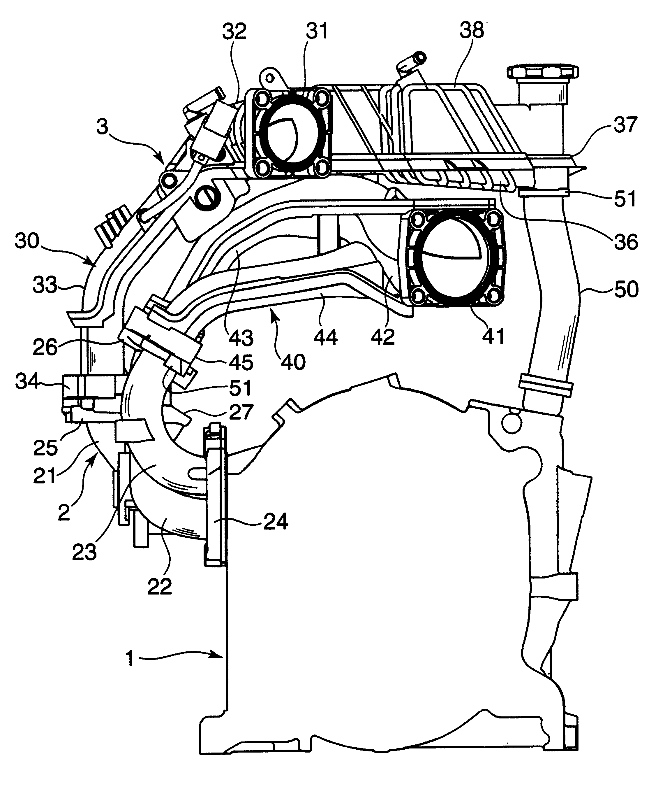
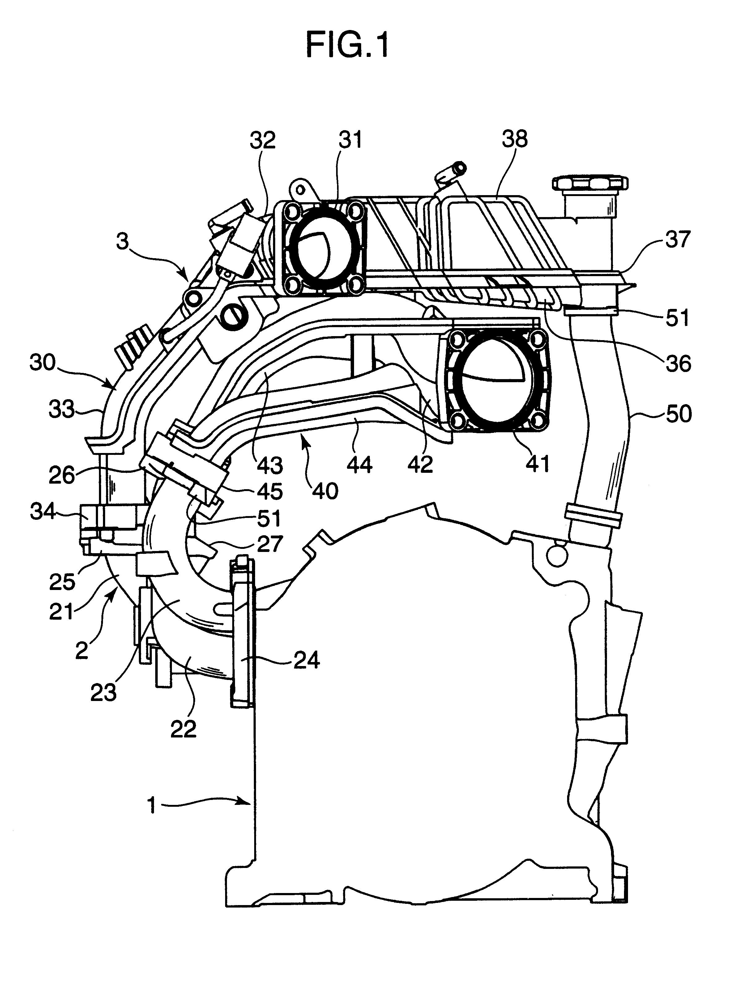
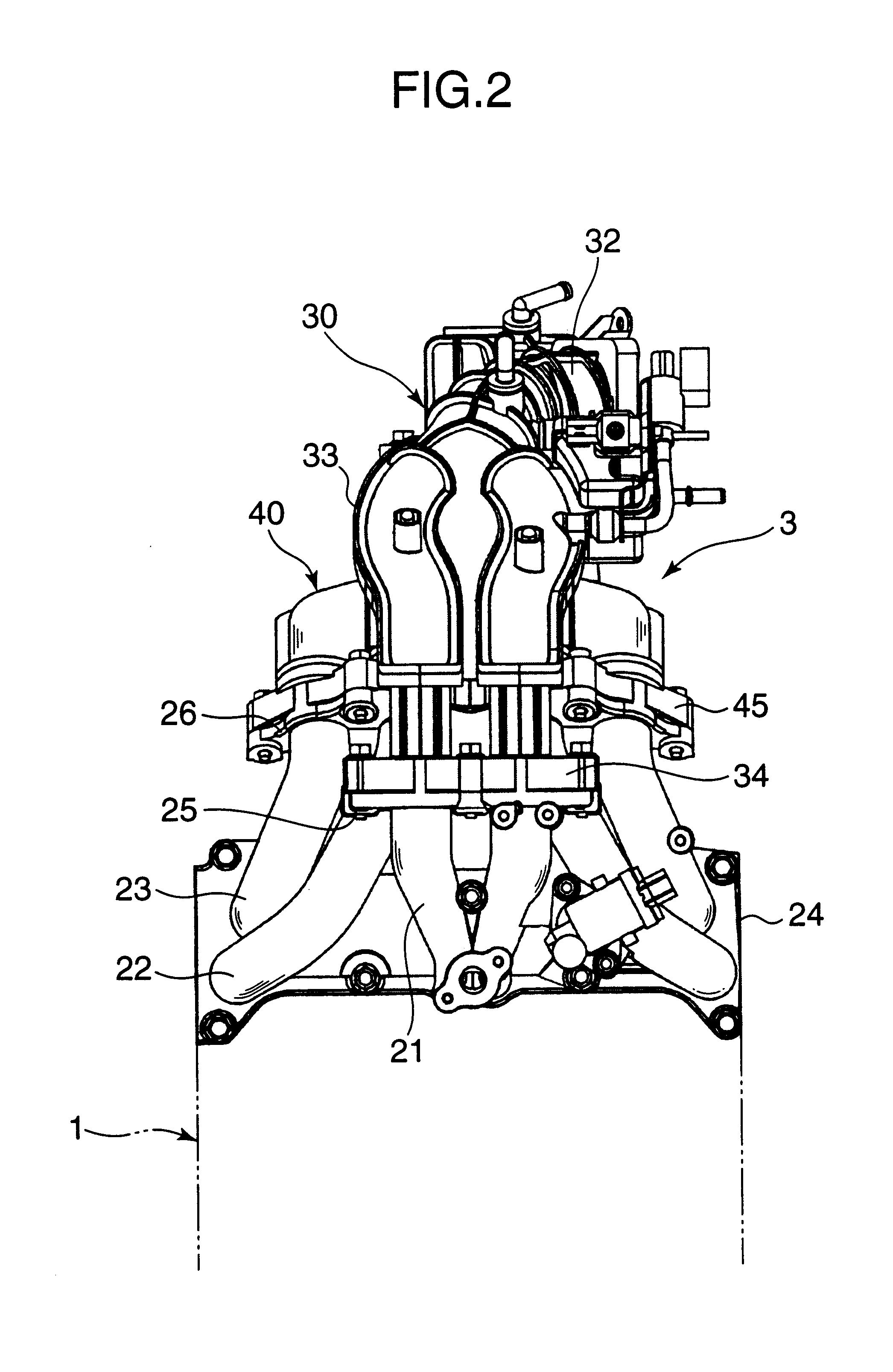
FIGS. 1 to 3 are diagrams showing the overall construction of an intake system according to the first embodiment of the invention as it is applied to a two-cylinder rotary engine of a motor vehicle. In these Figures, designated by the numeral 1 is an engine body of the rotary engine, designated by the numeral 2 is a downstream portion of an intake manifold extending from the engine body 1, and designated by the numeral 3 is an intake module in which a throttle body joint portion and an upstream portion of the intake manifold are formed in a single structure.

As shown in FIG. 4, the engine body 1 has a housing for two cylinders including an intermediate housing block 10, a pair of hollow rotor housing blocks 11 provided on both sides (left and right as illustrated in FIGS. 2, 3) and a pair of side housing blocks 12 located on the front and rear sides of the respective rotor housing blocks 11. An inner surface of each rotor housing b...

second embodiment

The second embodiment is also applied to a two-cylinder rotary engine of a motor vehicle of which engine body 1 has a structure similar to that of the first embodiment. FIGS. 7 and 8 are diagrams showing the overall construction of an intake system according to the invention. The intake system of this embodiment comprises an intake module 103 made of synthetic resin material and a downstream portion 102 of an intake manifold formed of cast aluminum. The intake module 103 includes a pair of intake air passages 133 instead of each combination of the primary intake air passage 33 and the secondary intake air passage 43 of the first embodiment, in which parts constituting a throttle body joint portion and an upstream portion of the intake manifold excluding auxiliary secondary intake passages 144 are combined into a single structure. The downstream portion 102 of the intake manifold includes a pair of downstream side secondary intake passages 122 connected to corresponding downstream si...


PUM

PropertyMeasurementUnit
pressure-aaaaaaaaaa
pressureaaaaaaaaaa
stiffnessaaaaaaaaaa

Abstract

An intake system of an engine comprises an intake module, in which a throttle body joint portion and an upstream portion of an intake manifold are formed in a single structure, and a downstream portion of the intake manifold extending from an engine body. A downstream end of the intake module is joined to the downstream portion of the intake manifold and an end portion of the intake module opposite to its portion joined to the downstream portion of the intake manifold is connected to an uppermost part of an oil filler pipe which is connected to the engine body. In this construction, the intake module is supported by the engine body via the oil filler pipe.

Description

BACKGROUND OF THE INVENTION AND RELATED ART STATEMENT1. Field of the InventionThe present invention relates to an intake system of an engine. More particularly, the invention pertains to a structure including an intake module in which a throttle body joint portion and an upstream portion of an intake manifold are formed in a single structure and a downstream portion of the intake manifold that is connected to the intake module.2. Description of the Related ArtVarious intake system designs for an engine have been proposed in recent years, in which an intake system including an intake manifold or part of an intake manifold is formed of synthetic resin material. When using the synthetic resin material in the intake system, it is essential to design the system in such a way that it has adequate stiffness for supporting the intake manifold and its associated parts.An example of a conventional support mechanism for an intake system is proposed in Japanese Unexamined Patent Publication No....

Claims


Application Information

Patent Timeline
Patent Type & Authority Patents(United States)
IPC IPC(8): F02B53/00F02M35/10F02B27/02F01M11/04F02B53/04F02M35/104
CPCF02B53/00F02M35/10032F02M35/10111F02M35/10131F02M35/10144F02M35/10255F02M35/10321F02M35/10327F02M35/10347F02M35/112F02B27/021F02B27/0242F02B27/0252F02B27/02F02B2053/005F02M35/10386F05C2225/08Y02T10/17Y02T10/146Y02T10/12
Inventor FUJIHIRA, SHINJIYAMADA, MASANAOYOKOO, TAKESHIOKAZAKI, SHUNKIKINOSHITA, HIROSHI
Owner MAZDA MOTOR CORP
Why Eureka
Try Eureka