Light guide plate, surface light source device and display

a surface light source and light guide technology, applied in waveguides, lighting and heating apparatuses, instruments, etc., can solve the problems of inefficient direction conversion, unsatisfactory brightness, and very irrational orientation of micro-reflectors, and achieve bright display and high efficiency

Inactive Publication Date: 2004-06-08
ENPLAS CORP
View PDF21 Cites 59 Cited by
  • Summary
  • Abstract
  • Description
  • Claims
  • Application Information

AI Technical Summary

Benefits of technology

An object of the present invention is to provide at light guide plate suitable for introducing light from a plurality of input portions using point-like light sources, a surface light source device and a display employing the light guide plate. Viewing from another angle, the present invention aims to provide a light guide plate and a surface light source device which are capable of outputting an illumination light at a high efficiency and to realize a bright display by applying them to a display.
This enables the micro-reflectors to have orientations determined in consideration for situation of each region provided by the above division. In other words, micro-reflector orientations can be determined, for each region, depending on which input portion should be aimed by micro-reflectors in each region. As a result, an efficient direction conversion into a desirable direction (typically, a generally frontal direction) is effected by the micro-reflectors.
This enables the micro-reflectors to have orientations determined in consideration for not only situation of each region provided by the above division but also situation around boundaries among the respective regions. That is, a more efficient and uniform emission promotion is realized because of avoiding affection which could be caused by a sharp changing of orientation state around the boundaries among the respective regions.
That is, without a particular need of light propagation direction modifying member such as prism sheet, the surface light source device is capable of providing a sufficient illumination output directed to a desired direction (usually, a generally frontal direction and the display can have a liquid crystal display panel illuminated efficiently by the surface light source device.

Problems solved by technology

As known well, a simply transparent light guide plate without any modification is capable of deflecting light little, providing a unsatisfactory brightness.
However, a problem arises if the above-proposed prior art is applied to a case where a plurality of point-like light sources are adopted as primary light source, a problem arises.
Therefore, some areas have micro-reflectors provided with very irrational orientations.
This brings an inefficient direction-conversion and a direction-conversion into an undesirable direction, possibly affecting emission of inner propagation light.

Method used


Image

  • Light guide plate, surface light source device and display
  • Light guide plate, surface light source device and display
  • Light guide plate, surface light source device and display

Examples


first embodiment

(1) First Embodiment

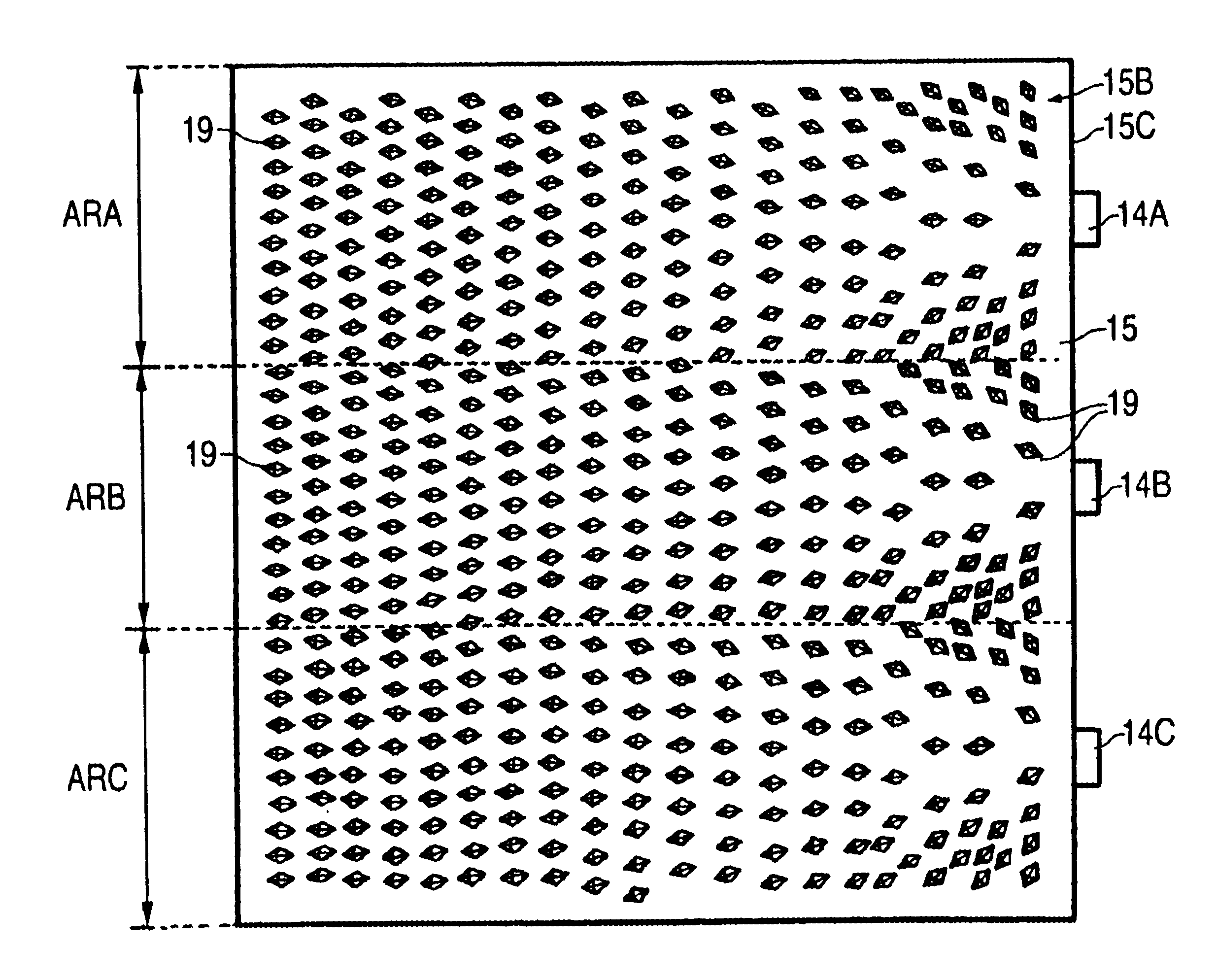
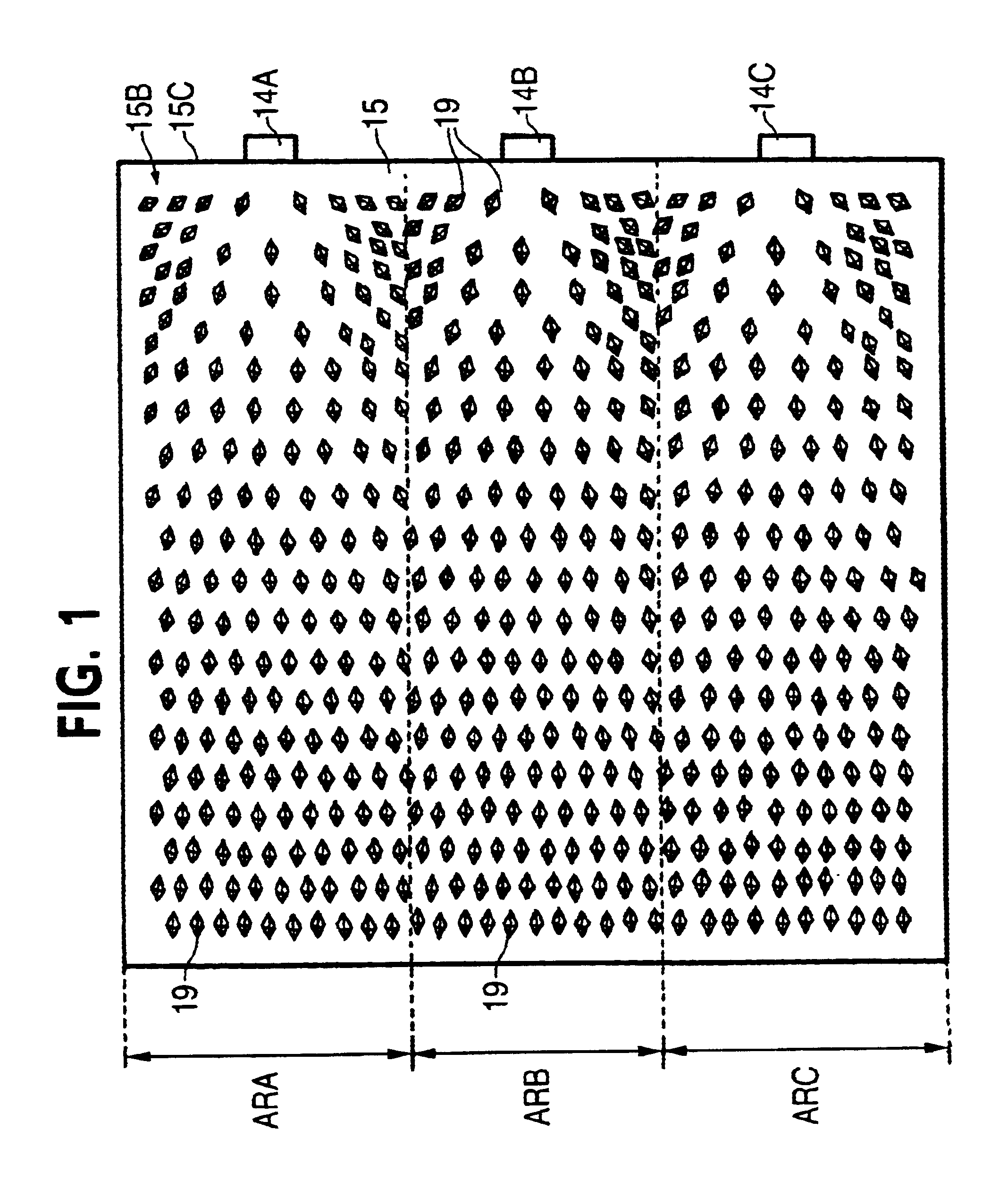
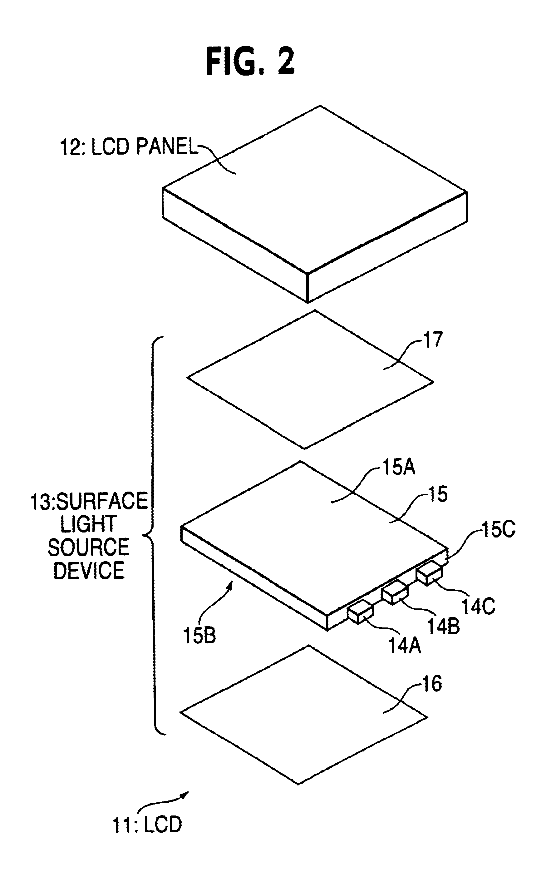
FIG. 2 is an exploded perspective view of the liquid crystal display of the first embodiment. A liquid crystal display 11 which is applied, for example, to a portable telephone, has a liquid crystal display panel 12 illuminated by a back-lighting surface light source device 18. The light source device 18 has a light guide plate 15. The light guide plate 15 is provided input portions at three locations along one end face and light emitting diodes as point-like light sources 14A, 14B and 14C are disposed at each of the input portions.

The light guide plate 15 have major faces one of which provides an emission face 15D along which a light diffusion sheet 17 is disposed. A reflection sheet 16 is disposed along a back face 15B opposite with emission face 15A. The reflection sheet 17 is made of a white sheet member, reflecting and returning a leaking light once escaping through the back face 15B into the light guide plate 15, thereby avoiding loss of illumination light....

second embodiment

The second embodiment is an embodiment such that the first embodiment (light guide plate 15) is further improved. That is, forementioned division (ARA to ARC) tends to cause characteristics of the emission to show a sharp changing around a boundary between the region ARA and the region ARB adjacent to the region ARA. It is found that this is apt to bring an unnatural emission around the boundary depending on viewing angles.

Further, if the LEDs 14A to 14C are different in emission intensity, the regions ARA to ARC have differences among them in brightness and it is found that the differences are easily observed, because each of the LEDs 14A to 14C carries out light supplying to each of the regions ARA to ARC independently.

Thus the second embodiment somewhat relaxes the above independent allotting relation between the regions and the input portion to suppress the above problem.

As shown in FIG. 4, the input portions are arranged in the same manner as compared with the first embodiment....


PUM

PropertyMeasurementUnit
distanceaaaaaaaaaa
inner-reflection slopeaaaaaaaaaa
inner-reflectionaaaaaaaaaa

Abstract

A surface light source device and display utilize a light guide plate provided with micro-reflectors arranged in an orientation suitable for a plurality of input portions having point-like light emitters, respectively. A light guide plate 15 has a back face divided into areas ARA to ARC to each of which each input portion having each of LEDs 14A to 14C is shared. Micro-reflectors 19 in each of areas ARA to ARC are orientated as to be directed to each of LEDs 14A to 14C correspondingly, effecting an effective direction conversion. Emitted light is incident to a liquid crystal display panel generally at a right angle via a light diffusion sheet. Some micro-reflectors 19 in each of areas ARA to ARC may be arranged as to be directed to an adjacent input portion. Micro-reflectors may be shaped like quadrangle pyramid projections, cylindrical dents or V-shaped dents.

Description

1. Field of InventionThe present invention relates to a light guide plate emitting light from an emission face after applying direction-conversion within the light guide plate to light supplied thereto sideways, and to a surface light source device and display employing the light guide plate.2. Related ArtA well-known technique gives a surface light source device that employs a light guide plate having a side part for light introduction and an emission face provided by one of two major faces (i.e. faces larger than end faces), the surface light source device being applied to various uses such as back-lighting for a liquid crystal display. A surface light source device of such a type has a basic performance greatly depending on a light guide plate employed therein.A basic function of a light guide plate is to change a propagation direction (roughly in parallel with an emission face of the light guide plate) of light introduced into the light guide plate through a side end face so tha...

Claims


Application Information

Patent Timeline
Patent Type & Authority Patents(United States)
IPC IPC(8): F21V8/00G02B6/42G02B6/00F21Y101/02G02F1/1335G02F1/13357
CPCG02B6/0018G02B6/0021G02B6/0036G02B6/0061G02B6/0068Y10S385/901G02F1/1335
Inventor OHKAWA, SHINGO
Owner ENPLAS CORP
Why Eureka
Try Eureka