
Automatic gain control system and method for a ZIF architecture

a gain control system and architecture technology, applied in the direction of gain control, digital transmission, transmission, etc., can solve the problems of excessive dc components, relatively simple actions become more complicated, and the 2-5 ghz band is relatively noisy with significant interferen

Inactive Publication Date: 2004-06-08
M RED INC
View PDF21 Cites 124 Cited by
  • Summary
  • Abstract
  • Description
  • Claims
  • Application Information

AI Technical Summary

Problems solved by technology

The 2-5 GHz bands are relatively noisy with significant amounts of interference.
These relatively simple actions become more complicated when operating with a ZIF architecture.
ZIF architectures, however, suffer from excessive DC components and DC can be adversely impacted by poor AGC control.
Because the DC voltage levels can become excessively large in the ZIF radio, the signals of interest become invisible and difficult to detect and acquire.
The primary problem with the ZIF architecture is the development of DC offsets at baseband that degrade signal-to-noise ratio (SNR), which is directly related to performance of the system.
It has been determined, however, that at such high gains (50 dB or more), increasing the gain by 10 dB may increase DC from 500 millivolts (mV) to 5 V, which is an increase of over 4 V. The ADC, however, is generally limited to a relatively small voltage range (e.g., approximately 0.5 V), so that excessive DC overwhelms the loop and causes instability and potential operation failure.
However, AC coupling results in filtering that tends to filter out low frequency content.
Within this range, however, the settling time is too long, such as on the order of approximately 100 microseconds (.mu.s), which is not practical in a bursty environment such as packet-based communications.
The settling time is limited due to the bursty nature of communication.
While this appears to be a viable solution and has been used in the past, it required a significant amount of time.

Method used


Image

  • Automatic gain control system and method for a ZIF architecture
  • Automatic gain control system and method for a ZIF architecture
  • Automatic gain control system and method for a ZIF architecture

Examples


Embodiment Construction

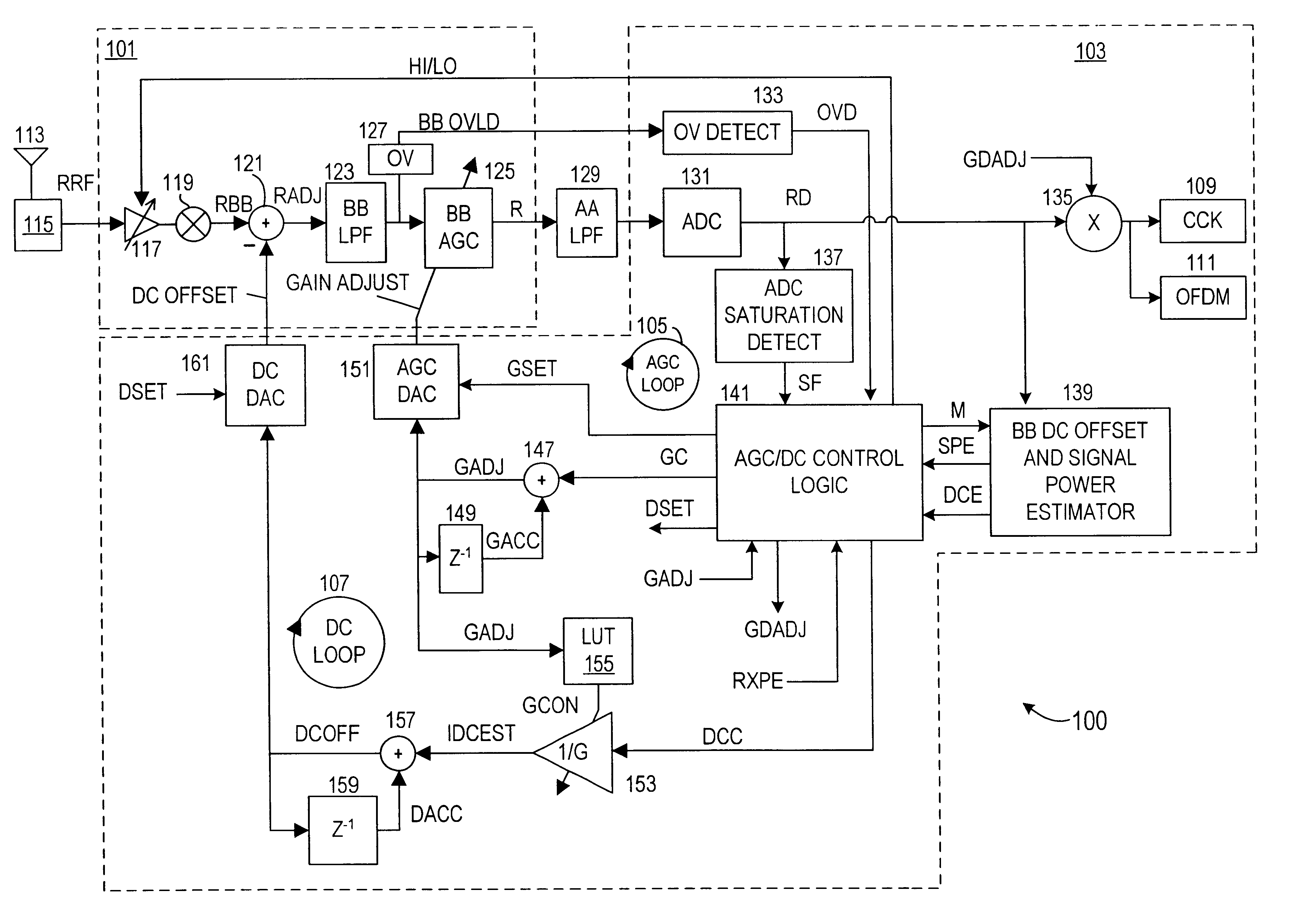
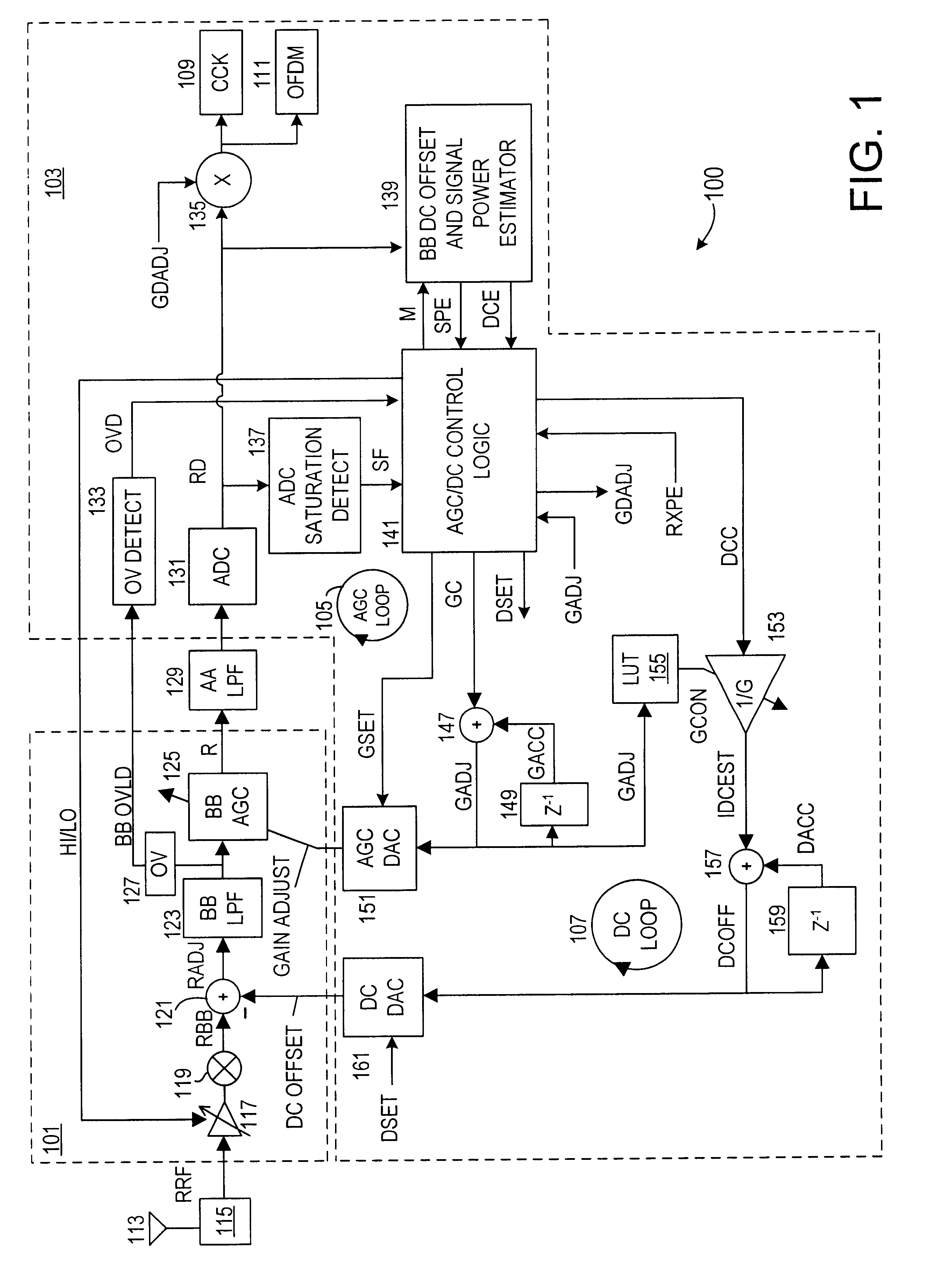
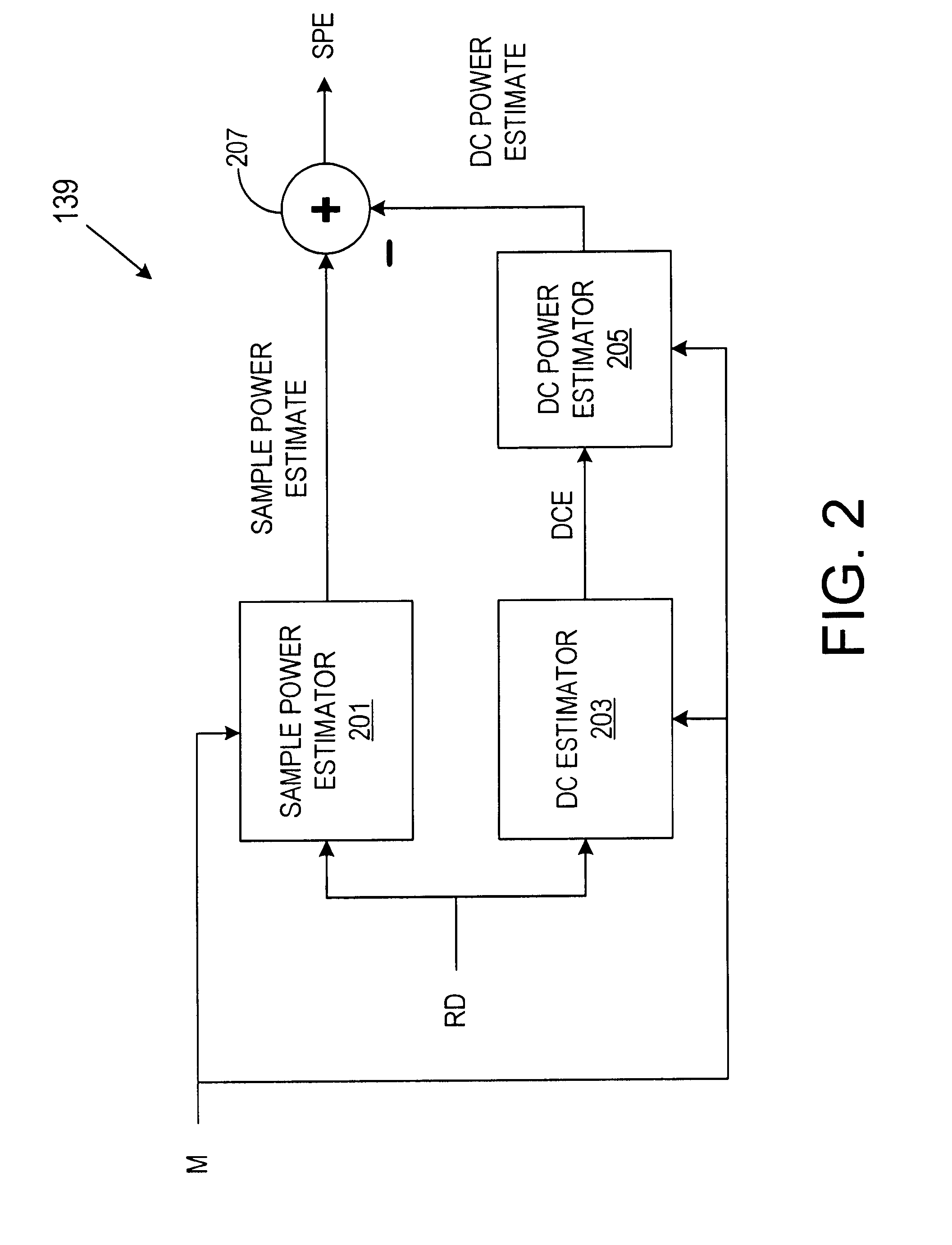
FIG. 1 is a simplified schematic and block diagram of a zero intermediate frequency (ZIF) wireless receiver 100 implemented according to an embodiment of the present invention for use in a Wireless Local Area Network (WLAN). It is understood, however, that the wireless receiver 100 is not limited to WLAN configurations, but instead may be employed in other types of radio or wireless communications for other types of applications. The wireless receiver 100 is the receive portion of a wireless transceiver that includes corresponding transmitter circuitry (not shown). The wireless receiver 100 may be designed in any one of several configurations, including, for example, personal computers, laptop computers, desktop computers, etc., printing devices including any type of printer technology, personal digital assistants (PDAs) or the like, scanners, fax machines, etc. The wireless receiver 100 may be configured as a plug-in peripheral or expansion card that plugs into an appropriate slot ...


PUM


Abstract

A system and method for controlling amplification of a signal received by a ZIF radio having a power level within a full power range relative to a minimum noise floor. The ZIF radio includes a ZIF receiver front end, an overload detector, an ADC, a saturation detector, a DC and power estimator, and control logic. The control logic utilized full visibility of the ADC to limit gain of the baseband amplifier to a maximum gain setting sufficient to view the minimum noise floor and to view a received signal having a power level within any of several segments of the power spectrum. The segmentation of the power spectrum is based on an overload condition of the ZIF receiver front end and a saturation condition of the ADC. The control logic further employs limited gain stepping of the baseband amplifier to avoid exceeding a DC budget of the ADC.

Description

The present invention relates to wireless communications, and more particularly to an automatic gain control system and method for a wireless communication device configured in a zero intermediate frequency (ZIF) architecture that utilizes a DC control loop to enable direct conversion of radio frequency signals to baseband frequency and a gain procedure that more accurately determines and controls DC voltage levels.DESCRIPTION OF RELATED ARTThe present invention is described in relation to a transceiver employed in a wireless local area network (WLAN) configuration. It is understood, however, that the present invention is not limited to WLAN configurations, but instead may be employed in other types of radio or wireless communications for other types of applications. A Zero Intermediate Frequency (ZIF) architecture is a wireless transceiver implementation that is utilized to obtain sufficient performance and higher data throughput at lower cost and power consumption. This is particu...

Claims


Application Information

Patent Timeline
IPC IPC(8): H03D3/00H04B1/30H03G3/30
CPCH03D3/008H03D3/009H03G3/3068H04B1/30H03D2200/0047H03G3/3052
Inventor WEBSTER, MARK A.YEH, ALEX C.GARRETT, ALBERT L.
Owner M RED INC
Learn More