Injection ratio control system for internal combustion engine

a technology of injection ratio control and internal combustion engine, which is applied in the direction of electrical control, process and machine control, instruments, etc., can solve the problems of excessive fuel injection, inability to control the injection ratio of the engine, and inability to inhibit the noise and vibration of the engin

Inactive Publication Date: 2004-06-15
DENSO CORP
View PDF4 Cites 18 Cited by
  • Summary
  • Abstract
  • Description
  • Claims
  • Application Information

AI Technical Summary

Benefits of technology

According to an aspect of the present invention, a main injection quantity command value for a main injection in a multi-injection is calculated in accordance with an operating state or operating conditions of an internal combustion engine. An injection frequency per combustion in the multi-injection (a multi-injection frequency) is regulated so that the main injection quantity command value becomes equal to or greater than an N time(s) minimum guarantee determination value. Thus, vanish of a pilot injection or an excessive fuel injection in the pilot injection due to variation in hardware is prevented. As a result, the variation in the actual injection quantity or the injection frequency is prevented without reducing a noise reduction effect of the multi-injection.

Problems solved by technology

As a result, the noise and vibration of the engine are inhibited.
However, even if the minute injection quantity command value is calculated and outputted, the pilot injection may vanish or excessive fuel may be injected in the pilot injection due to variation in hardware.
As a result, fluctuation of drivability or emission may be caused.

Method used


Image

  • Injection ratio control system for internal combustion engine
  • Injection ratio control system for internal combustion engine
  • Injection ratio control system for internal combustion engine

Examples


first embodiment

(First Embodiment)

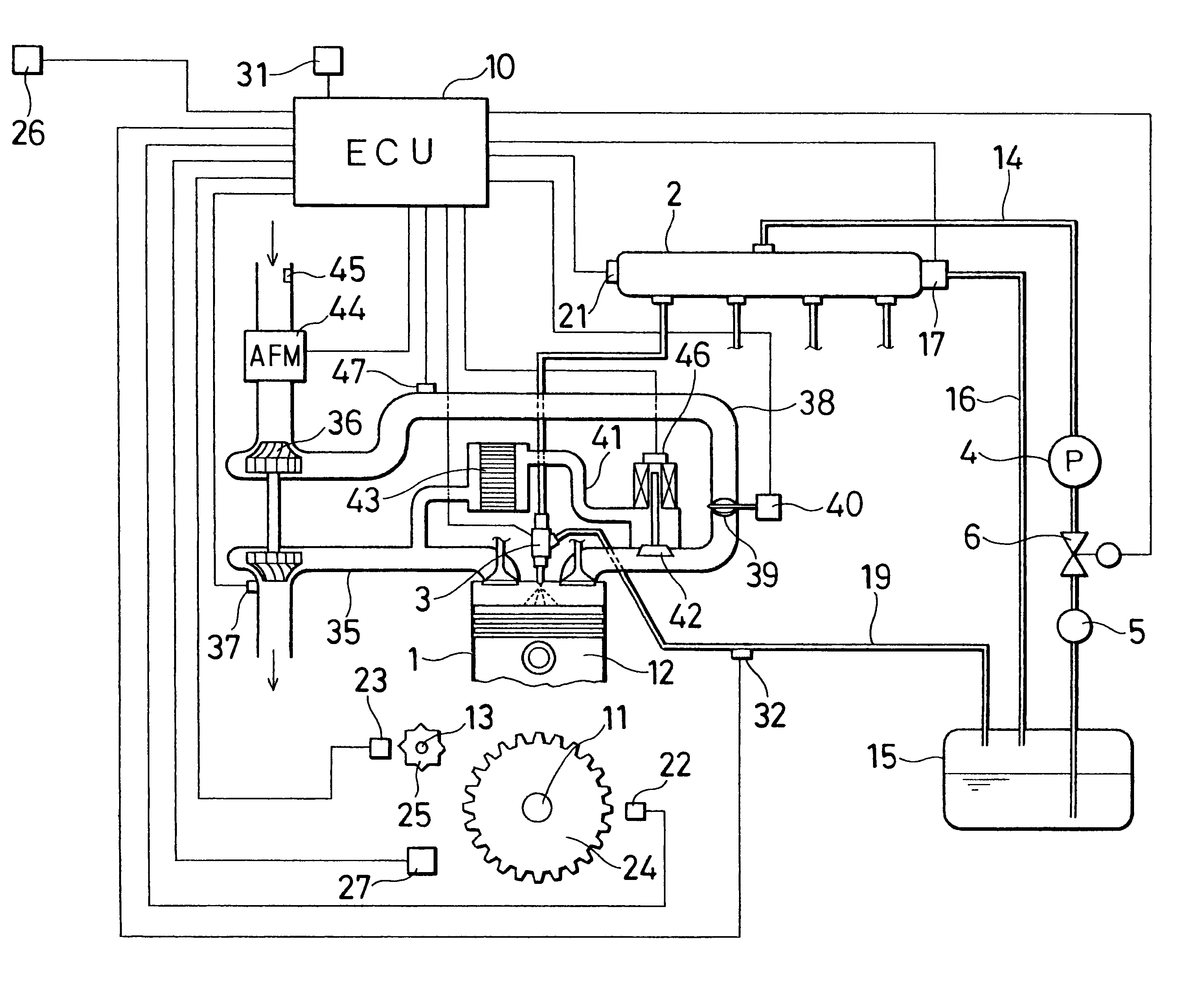
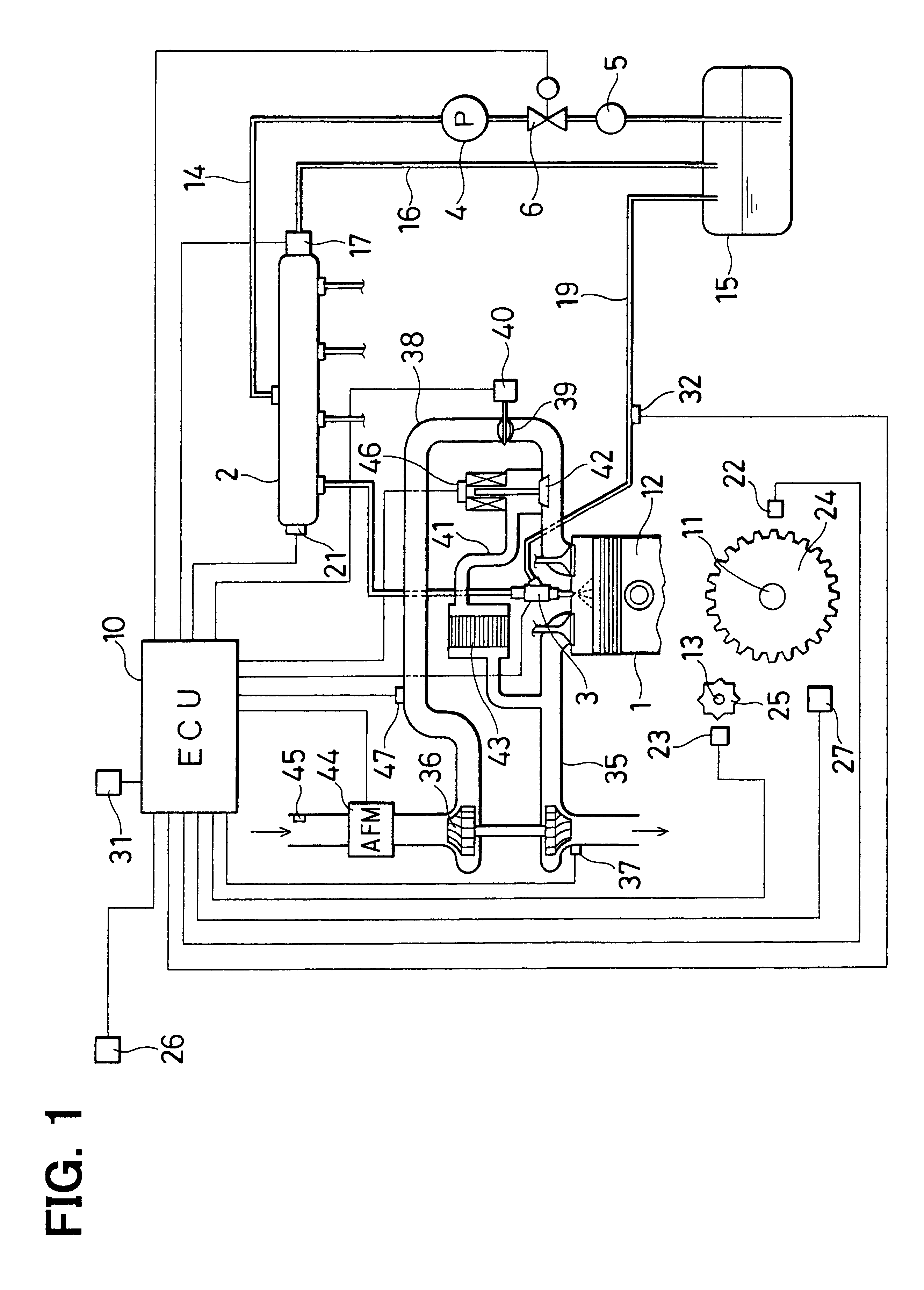
Referring to FIG. 1, an accumulation type fuel injection system according to the first embodiment is illustrated. The accumulation type fuel injection system has a common rail 2 as an accumulator, a plurality of (four, in the embodiment) injectors 3 having electromagnetic valves, a fuel supply pump 4 and an electronic control unit (ECU) 10. The common rail 2 accumulates fuel at a high pressure corresponding to a fuel injection pressure, at which the fuel is injected into respective cylinders of an internal combustion engine 1 such as a four-cylinder diesel engine mounted on a vehicle. The injectors 3 are respectively connected with the common rail 2 and inject the fuel into the respective cylinders of the engine 1. The supply pump 4 is rotated by the engine 1. The ECU 10 electronically controls the injectors 3 and the supply pump 4.

A piston 12 connected with a crankshaft 11 through a connection rod is slidably disposed in each cylinder of the engine 1.

The common ra...

second embodiment

(Second Embodiment)

Next, an injector injection quantity controlling method of the second embodiment for controlling a multi-injection frequency will be explained based on FIGS. 5 and 6.

When a routine shown in FIG. 5 is started after the FCCB correction or the ISC correction, the total injection quantity command value Qt is calculated like the first embodiment in Step S21. Then, it is determined whether the total injection quantity Qt is greater than an N times (five times, in the embodiment) injection permission determination value KQMIN5 or not in Step S22. If the result of the determination is "YES", N times (five times, in the embodiment) injections are permitted in Step S23. Then, the processing leaves the routine shown in FIG. 5.

If the result of the determination in Step S22 is "NO", the injection quantity command value Q1 is cleared (Q1=0) in Step S24. Meanwhile, it is determined whether the total injection quantity Qt is greater than an N minus one times (four times, in the e...


PUM


Abstract

An injection ratio control system for an internal combustion engine performs a multi-injection, in which multiple pilot injections and a main injection are performed. The system prohibits a first injection among the pilot injections if a main injection quantity command value for the main injection is less than an N time(s) minimum guarantee determination value. An injection quantity for the first injection is added to the injection quantity for the main injection. Thus, the system controls an injection frequency per combustion in the multi-injection to prevent the use of a minute main injection quantity command value equal to or less than the N time(s) minimum guarantee determination value. As a result, the main injection is prevented from vanishing.

Description

This application is based on and incorporates herein by reference Japanese Patent Application No. 2002-151254 filed on May 24, 2002.1. Field of the InventionThe present invention relates to an injection ratio control system for an internal combustion engine that drives injectors based on injection quantity command values such as an injector injection command pulse period, an injector energization period, an injector injection period, or an injector valve-opening period. The injection quantity command values are calculated from command injection quantity set in accordance with an operating state or operating conditions of the engine, and fuel injection pressure measured by a sensor and the like. Specifically, the present invention relates to a fuel injection system for an internal combustion engine capable of performing a multi-injection in which fuel is injected into cylinders of the engine in multiple times by driving electromagnetic valves of the injectors during a compression str...

Claims


Application Information

Patent Timeline
Patent Type & Authority Patents(United States)
IPC IPC(8): F02D41/40F02M45/02F02D41/38F02M47/00
CPCF02D41/403F02D41/402Y02T10/44Y02T10/40
Inventor ITO, YOSHIOTAKASHIMA, YOSHIMITSU
Owner DENSO CORP
Why Eureka
Try Eureka