Aerial vehicle controlled and propelled by oscillatory momentum generators and method of flying a vehicle

a technology of oscillatory momentum and generator, applied in the field of aircraft, can solve the problems of large and significant loss of efficiency, unsuitable application of these principles to miniaturized aircraft, and high cost of uav,

Inactive Publication Date: 2004-06-15
RAMOT UNIV AUTHORITY FOR APPL & IDUSTRIAL DEV
View PDF10 Cites 38 Cited by
  • Summary
  • Abstract
  • Description
  • Claims
  • Application Information

AI Technical Summary

Problems solved by technology

The aeronautical engineer has historically been faced with a tradeoff between physical storage space on an aircraft and the drag penalties associated with increasingly bluff bodies that inevitably accompany higher storage volumes.
However, application of these principles to miniaturized aircraft has not previously been achieved because conventional flight cannot be achieved at these small scales and low velocities.
Such a UAV is costly, large and significantly looses efficiency when reduced in size, i.e. such that its wings operate at Reynolds numbers of 100,000 or smaller.
However, this further miniaturization has not previously been successfully achieved because of the need to fly at large speeds to overcome the low efficiency imposed by the low Reynolds numbers.
Additionally, these devices are extremely fragile due to their combined structural complexity and imposed weight limitations.
This limits the degree of miniaturization, which can be implemented owing to torque forces about the axis of the rotor and it forces large empennage (which is even less efficient than the main wing due to the smaller size).
In addition, the rotors themselves increase the fragility of the UAV, limiting the range of applications to which they are suited.

Method used


Image

  • Aerial vehicle controlled and propelled by oscillatory momentum generators and method of flying a vehicle
  • Aerial vehicle controlled and propelled by oscillatory momentum generators and method of flying a vehicle
  • Aerial vehicle controlled and propelled by oscillatory momentum generators and method of flying a vehicle

Examples


example 1

Effects of Weight and Aspect Ratio

In order to illustrate basic aerodynamic advantages of a mUAV according to the present invention, consider estimates of Reynolds number, C.sub.L and thrust required (T.sub.R) as functions of flight speed (V), presented in FIGS. 6a-c respectively.

For purposes of comparison, the figures show calculations for three different configurations;

1) a conventional prior art mAV (weight W=0.1 kg, wing-span WS=0.15 m and aspect ratio AR=1; specifications approximately correspond to Lockheed Martin's MicroSTAR)

2) a light mUAV according to the present invention (i.e. WS=0.45 m, AR=4; W=0.225 kg)

3) a heavy mUAV according to the present invention (i.e. WS=0.45 m, AR=4; W=0.45 kg)

For all configurations, typical flight speeds are assumed to be approximately between 5 m / s and 25 m / s (see e.g. Spedding. and Maxworthy (1986) J. Fluid Mech., Vol. 165, pp. 247-272). FIG. 6a shows that the larger mUAVs are subjected to lower Reynolds numbers, for the flight speeds consider...

example 2

Theoretical Considerations in Predicting Flight Characteristics

The following equations present the method used for generating the curves in FIG. 6c (Adapted from Anderson (Ibid)) as well as all assumptions invoked.

A force balance shows that for level steady flight: ##EQU1##

where T and W are thrust and weight respectively. Therefore, the thrust required (T.sub.R) by the AFC devices employed in the present invention, for example, to overcome the total aircraft drag is ##EQU2##

Thus, for a given velocity, the lift coefficient is calculated from ##EQU3##

Therefore it is possible to calculate the total drag of the aircraft, i.e. ##EQU4##

where C.sub.D0 is the zero-lift parasite drag (typically 0.02 to 0.025 for conventional aircraft), e is the Oswald efficiency factor (usually .apprxeq.0.8 for conventional aircraft) and AR is the aspect ratio. It should be noted that C.sub.D0 for the mUAVs according to the present invention are lower since the aircraft is free of wing-body junctions, engine...

example 3

Previous Active Flow Control Limitations

Previously, it has been generally accepted that airfoil performance is significantly degraded below Re.about.O(10.sup.5). Further successive degradation occurs at Re=84,000 and 42,000, where many airfoils fail to generate useful lift.

Using an airfoil, originally designed as a flap (FIG. II.4a Now FIG. 7a), with chord length c=109 mm and maximum thickness (t / c).sub.max =17% (see Greenblatt, D. and Wygnanski, I., "Use of Periodic Excitation to Enhance Airfoil Performance at Low Reynolds Numbers" AIAA Journal of Aircraft, Vol. 38, No. 2, 2001, pp. 190-192.). The pictured airfoil has an interior plenum in fluid communication with a nominally two-dimensional, leading-edge slot (h=0.5 mm at x / c=2%) and is equipped with 18 surface pressure taps located on the center-span. Static and dynamic pressure measurements were made for 30,000.ltoreq.Re.ltoreq.150,000 at baseline and controlled conditions. Zero net mass-flux excitation (alternating air intake a...


PUM


Abstract

A vehicle capable of flight including at least one wing including at least one oscillatory momentum generator mounted therein. A thrust force from the oscillatory momentum generator is directed outwards over the wing causing a lift-generating air flow over a wing surface. A method of flying a vehicle including providing at least one wing having at least one oscillatory momentum generator mounted therein and applying a thrust force from the generator which is directed outwards over the wing and directed to the trailing edge so that a lift generating air flow is created.

Description

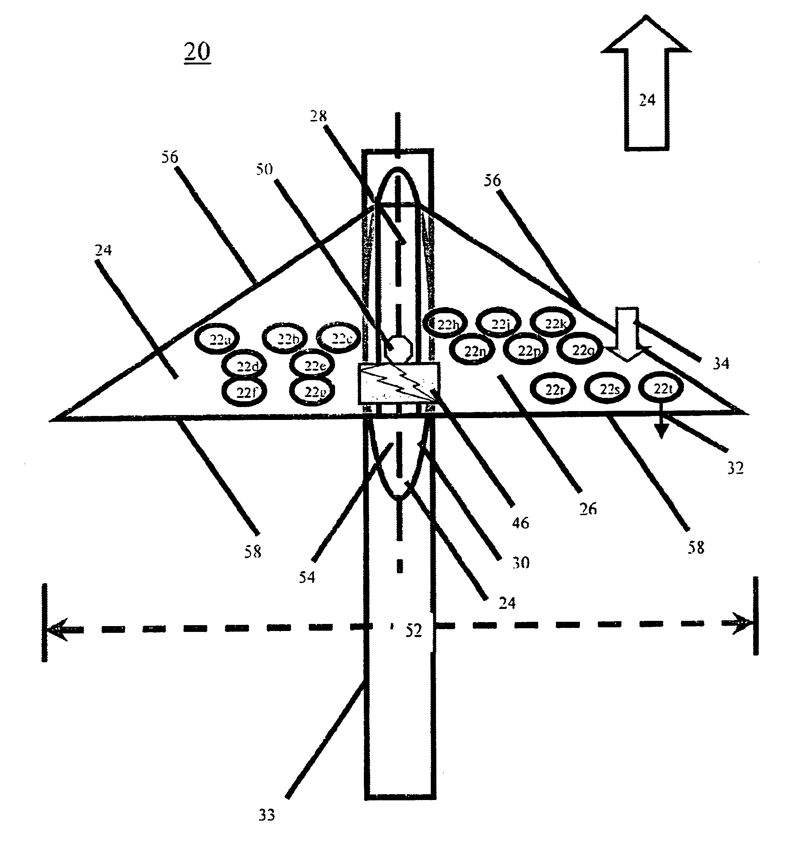
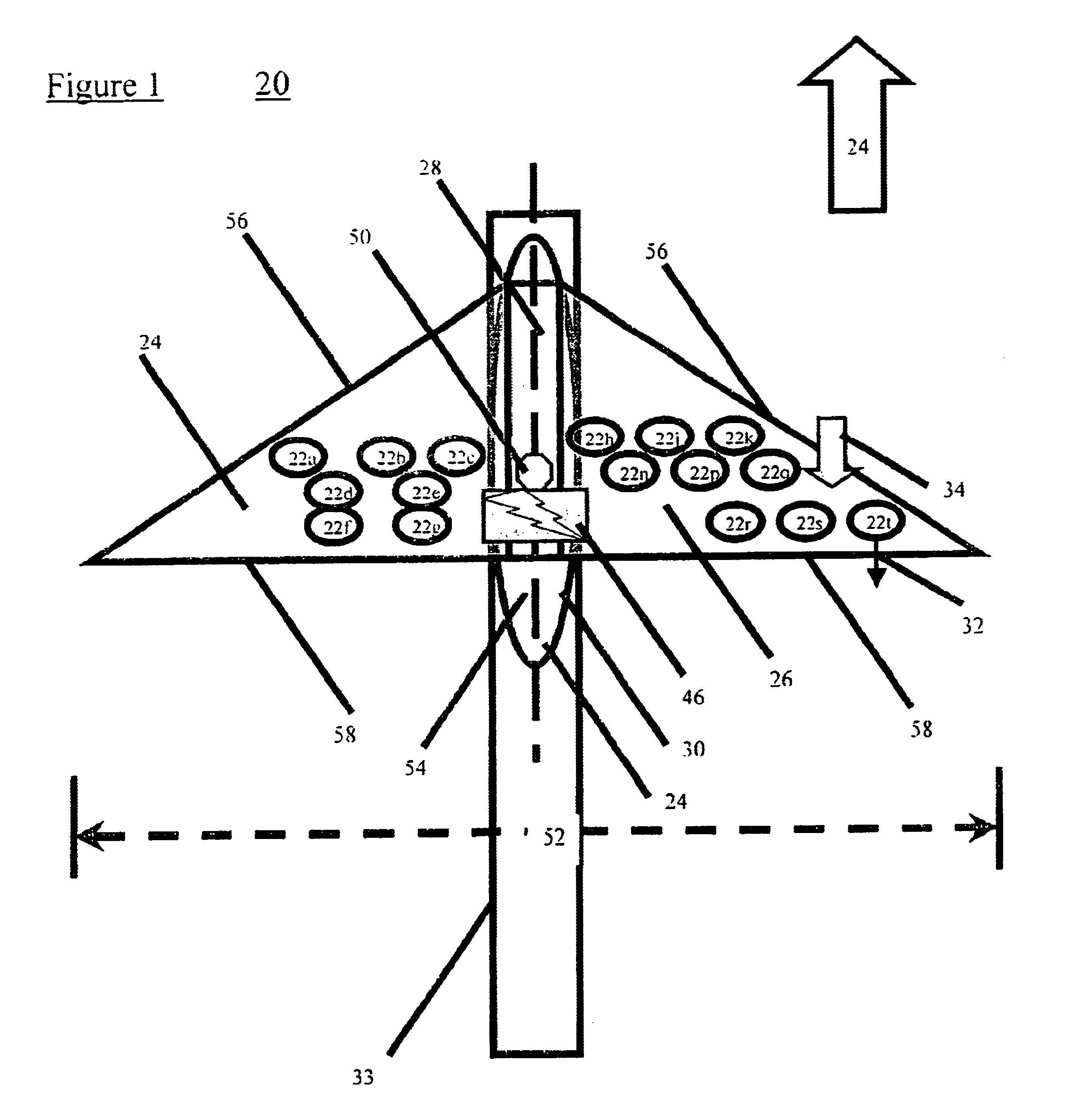
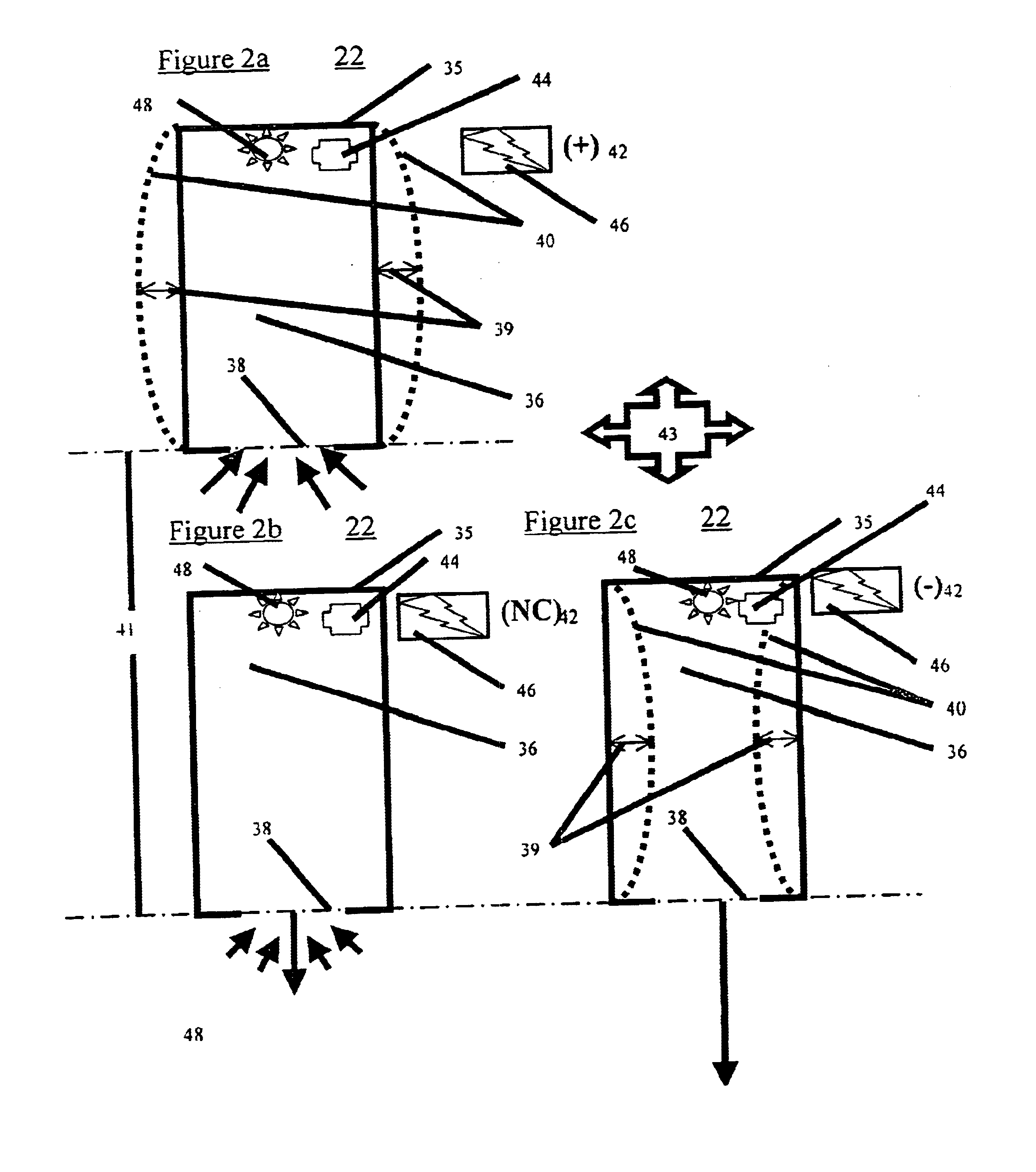
FIELD AND BACKGROUND OF THE INVENTIONThe present invention relates to an aerial vehicle controlled and propelled by oscillatory momentum generators and method of flying a vehicle and, more particularly, to the use of oscillatory momentum generators to sustain flight of a miniature or micro-miniature vehicle. The claimed invention is useful primarily in unmanned aerial vehicles (UAVs).The aeronautical engineer has historically been faced with a tradeoff between physical storage space on an aircraft and the drag penalties associated with increasingly bluff bodies that inevitably accompany higher storage volumes. A classic example of this tradeoff is embodied by the C-130J that employs a ramp at the rear of a wide fuselage that introduces a moderate drag penalty.In an attempt to resolve this disparity, Goldshmied (Goldschmied, F. R., "Fuselage Self-Propulsion by Static-Pressure Thrust: Wind Tunnel Verification", AIAA Paper 87-2935, 1987.), studied the ideal shape of a thick body of rev...

Claims


Application Information

Patent Timeline
Patent Type & Authority Patents(United States)
IPC IPC(8): B64C39/00
CPCB64C39/001H02K41/00B64C29/005
Inventor SEIFERT, AVRAHAMGREENBLATT, DAVIDWYGNANSKI, ISRAEL
Owner RAMOT UNIV AUTHORITY FOR APPL & IDUSTRIAL DEV
Why Eureka
Try Eureka