Waste assembly allowing adjustable fitment of a floor waste or appliance

a technology for waste and appliance, applied in domestic plumbing, water/sludge/sewage treatment, sewerage structures, etc., can solve the problems of less than aesthetically pleasing, no teaching versatility of fitment, and almost no flexibility

Inactive Publication Date: 2004-06-29
REED AVA
View PDF18 Cites 49 Cited by
  • Summary
  • Abstract
  • Description
  • Claims
  • Application Information

AI Technical Summary

Benefits of technology

This allows floor cladding such as tiles to be located according to a selected pattern and not dictated by the positioning of the grate. Thus the grate can be positioned selectively to accommodate tile joins by avoiding them altogether or intersecting with them. This also allows selective positioning of a waste generating appliance or floor grate without requiring alignment between said grate or appliance outlet and an inlet to drainage plumbing infrastructure.
According to another aspect, the present invention provides a waste body for use with an assembly for receiving a floor grate or waste generating appliance outlet which connects with an inlet to drainage plumbing in a building; thereby obviating the necessity for the floor grate or outlet of said appliance to align with said inlet.
These arrangements have the added advantage of preventing unwanted interruption to a predetermined floor cladding pattern, layout or configuration. Preferably the grate or appliance outlet may be selectively positioned to avoid or alternatively intersect with a join or joins in said floor cladding.
In another form the present invention comprises; a waste body for use with an assembly for colon and discharge of waste from a waste generating appliance or floor waste, the waste body comprising an open mouth reservoir for receiving said waste and including an outlet for discharging said waste received in said reservoir, the waste body further including a bearing surface which receives an insert proportioned to cover said mouth, the insert adapted to receive a grate or outlet of a waste generating appliance positioned in the insert such that the outlet of the waste body connects to and aligns with an inlet to underfloor drainage plumbing; wherein the dimension of said mouth is such that said grate or appliance outlet need not align with said inlet to said underfloor plumbing thereby allowing flexibility in the positioning of said floor grate or appliance within the limits of a periphery of said waste body.
Preferably, the insert is set in the waste body with clearance for seepage via said shoulder In another form the present invention comprises: a waste assembly for receiving and discharging waste from a waste producing appliance, surface drain or the like in communication with the assembly; the assembly including; a waste body having an open mouth defining a recess for receiving said waste, and an outlet capable of connection to an inlet of drainage plumbing infrastructure allowing discharge of said waste; a closure member supported by the waste body for closing said mouth and which receives said surface drain or an outlet of said waste producing appliance; wherein the closure is proportioned such that an installer of said surface drain or outlet of said appliance may position said drain or appliance outlet at any selected position bounded by the periphery of said waste body thereby obviating the need for direct connection and / or axial alignment between said surface drain or appliance outlet and said plumbing infrastructure.
According to one embodiment, the grate assembly is clamped with a lock nut to a prefabricated shower tray. In another embodiment the assembly is set in an adhesive or cementitous material. A thread on an outer surface of the retaining body facilitates anchorage of the assembly. Preferably, the closure comprises a roof including a contoured surface conducive to drainage and leg members supporting said roof and which engage a recess in said retaining body. Preferably, said legs bear on an upper surface of said strainer plate and are releasable from said recess in said retaining body by rotation.

Problems solved by technology

Adjustment of the waste or appliance outlet to match drainage plumbing infrastructure has in the past been inhibited once underfloor drainage plumbing is in place as there is almost no flexibility in positioning of above floor waste generating appliances or floor wastes.
According to the prior art the final position of a floor waste is dictated by the underfloor plumbing infrastructure, but the floor cladding must then be adjusted to suit the waste position which can often result in less than aesthetically pleasing results.
The arrangement described in that patent allows interchangability of two top members but is not intended as a waterproofing solution.
Nor does it teach versatility of fitment at the distal end of a downpipe.
Thus, in the prior art floor waste arrangements there is almost no flexibility as to the location of the grate once the underfloor plumbing infrastructure is set and this is usually completed first.
This absence of flexibility means that a waste or appliance can only be located where it will align with an inlet to the main drainage plumbing and that subsequent work such as floor tiling must accommodate the waste or appliance outlet in that the tiling patterning is in most cases interrupted such that the result is aesthetically unacceptable.

Method used


Image

  • Waste assembly allowing adjustable fitment of a floor waste or appliance
  • Waste assembly allowing adjustable fitment of a floor waste or appliance
  • Waste assembly allowing adjustable fitment of a floor waste or appliance

Examples


Embodiment Construction

The present invention will now be described in more detail according to a preferred but non limiting embodiment and with reference to the accompanying drawings wherein;

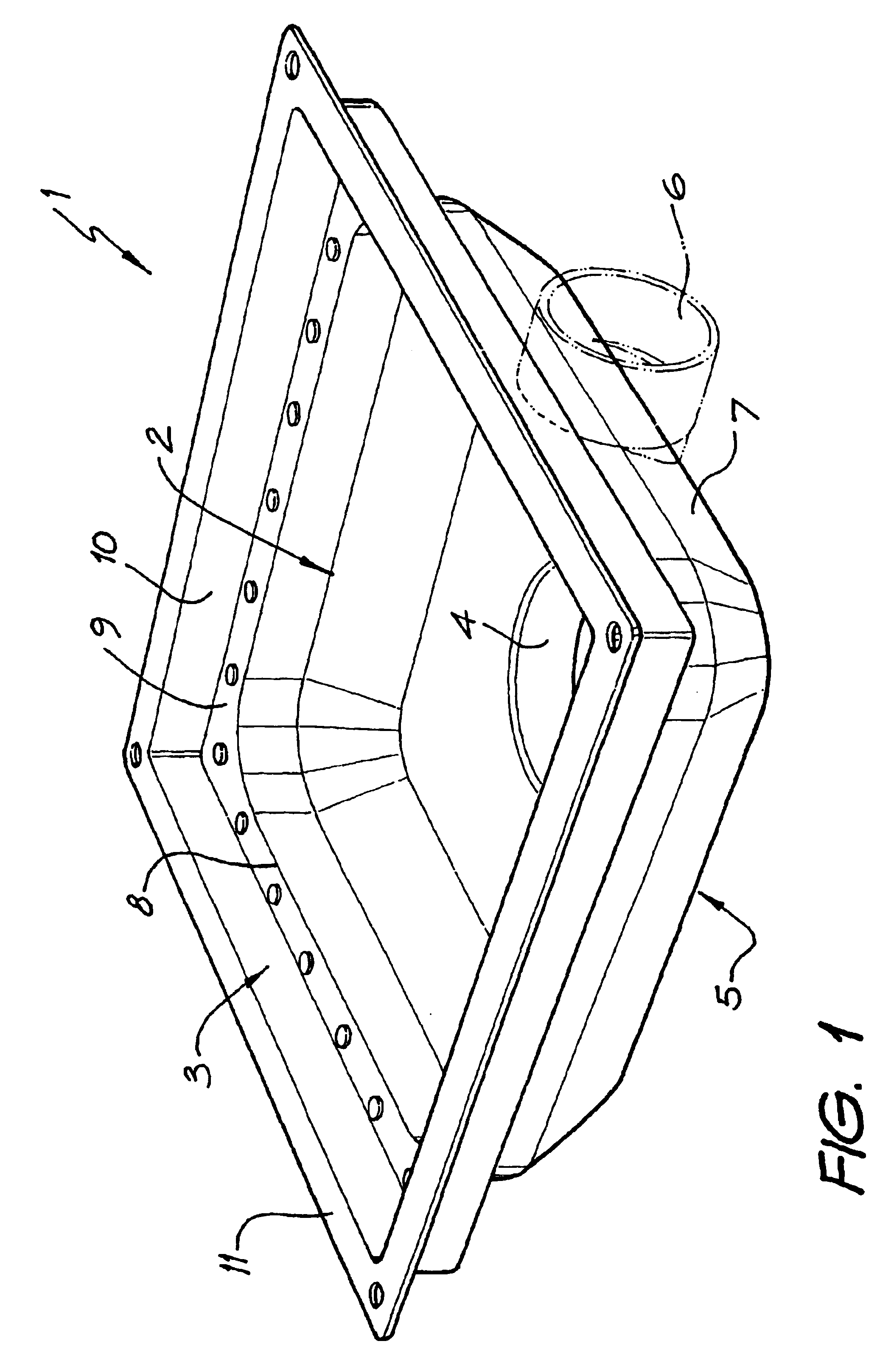
FIG. 1 shows a perspective view of a preferred embodiment of a waste body for use in the waste assembly according to the invention;

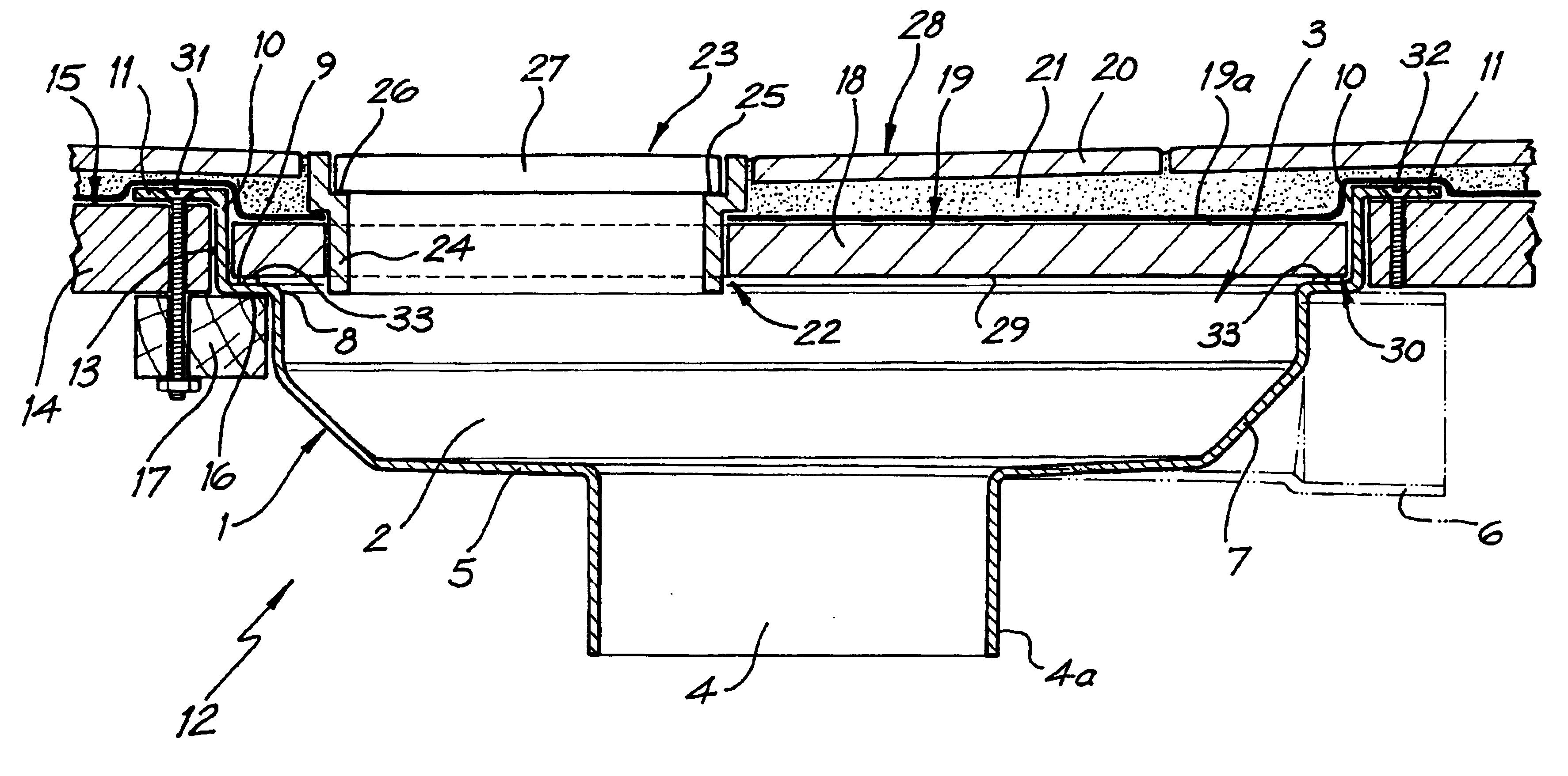
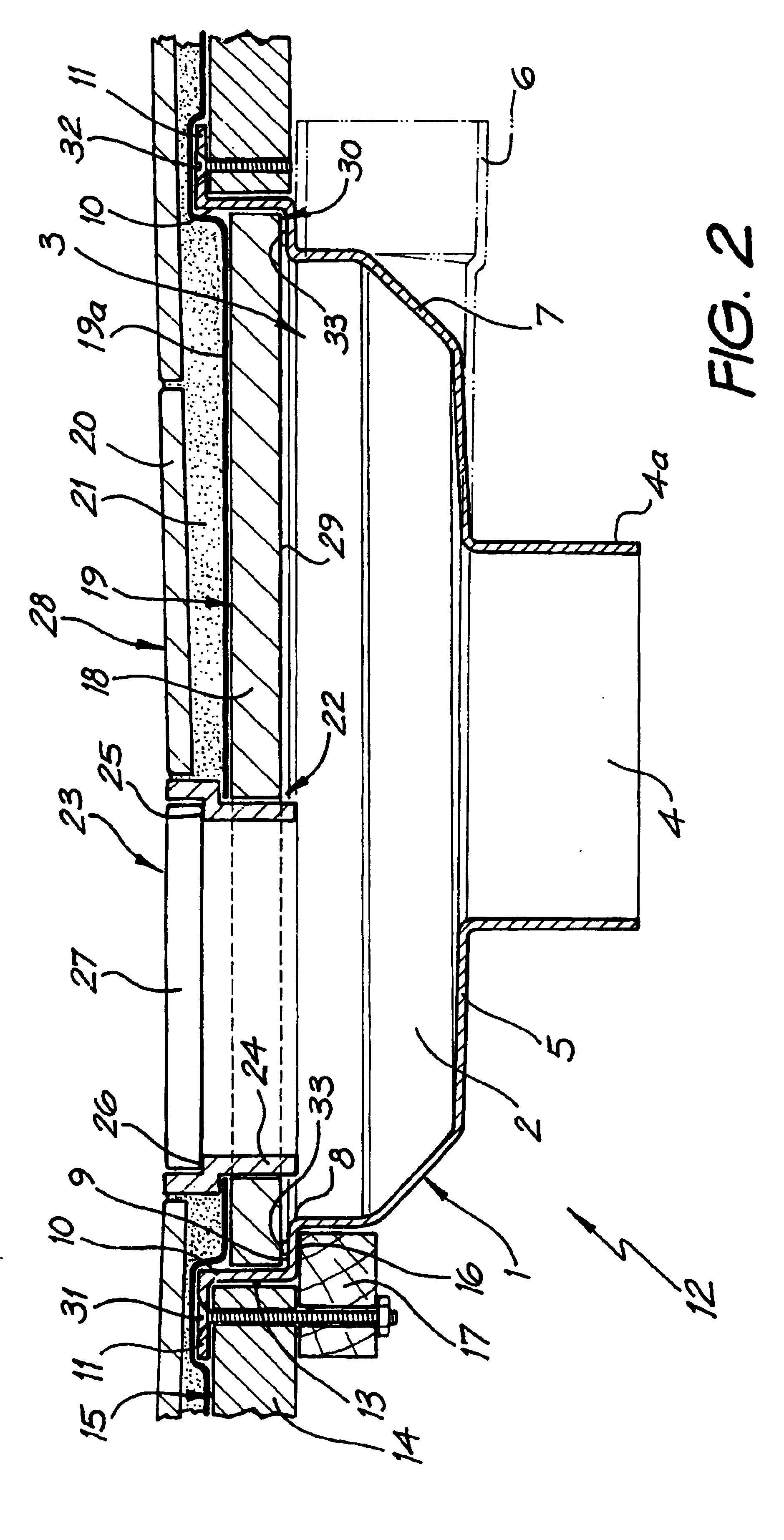
FIG. 2 shows a sectional view through a floor mounted waste assembly according to a preferred embodiment of the invention.

FIG. 3 shows a cross sectional elevation of an alternative waste body preferably for use where a waste generating appliance is connected to a waste assembly;

FIG. 4 shows a perspective view of the waste body of FIG. 3

FIG. 5 shows a cross sectional elevation of a waste body of a type similar to that in FIG. 3 this time with a side outlet;

FIG. 6 shows a perspective view of the waste body of FIG. 5 according to a preferred embodiment.

FIG. 7 shows a cross sectional elevation of a grate assembly according to a preferred embodiment;

FIG. 8 shows an exploded view of the grate as...


PUM


Abstract

A floor or ground surface waste assembly for receiving floor or appliance generated waste including a waste body (1) defining a waste collecting receptacle (2). The waste body (1) includes an open mouth (3) for receiving waste products from a floor grate or appliance, an outlet connected to said reservoir in communication with said mouth for connecting the waste assembly to a waste drainage line for eventual discharge of said waste, said waste body (1) also including a bearing surface (9) extending at least partially about the periphery of said waste body (1) and which is capable of supporting directly or indirectly a grate or appliance outlet; wherein said mouth (3) is proportioned to allow selective positioning of a grate or appliance outlet within said mouth within the limits of the periphery of the waste body such that said selective positioning of said grate or appliance outlet obviates the necessity for said appliance outlet or grate to align axially with or be directly connected to underfloor drainage plumbing.

Description

The present invention relates to drainage apparatuses and more particularly to a waste assembly for use with waste generating appliances and as a surface drain including a reservoir which accommodates a floor waste or waste discharge line from an appliance in a selected location within the periphery of the reservoir.PRIOR ARTThere are in existence a wide variety of surface drains and floor wastes and waste outlets associated with appliances which link directly or indirectly with plumbing infrastructure in a building. These are found in public and private installations alike and are usually positioned at a low point in the drainage network. Generally in the case of floor drains and wastes these include a grate which finishes the assembly and allows ingress of surface waste water.One such floor waste is disclosed in German specification D E 4115638. This document discloses a metal drain gutter inserted in a concrete or plaster floor and includes a grill which covers the opening but al...

Claims


Application Information

Patent Timeline
Patent Type & Authority Patents(United States)
IPC IPC(8): E03F5/04
CPCE03F5/0408E03F2005/0413E03F2005/0415
Inventor REED, SELWYN
Owner REED AVA
Why Eureka
Try Eureka