Control of airway pressure during mechanical ventilation

a technology of mechanical ventilation and airway pressure, which is applied in the direction of respirator, trachea tube, life-saving device, etc., can solve the problems of pressure artifacts, catheter tip malfunction, and impression of patient resistance chang

Inactive Publication Date: 2004-07-06
UNIVERSITY OF MANITOBA
View PDF16 Cites 81 Cited by
  • Summary
  • Abstract
  • Description
  • Claims
  • Application Information

AI Technical Summary

Benefits of technology

A modification to standard ET tubes is provided herein which permits the long term monitoring of pressure at the trachea and which eliminates many of the problems described above. Accordingly, in this aspect of the invention, there is provided an endotracheal tube for patient ventilation, comprising an elongate wall, a chamber formed in the wall adjacent the end to be located in the patient airway with the chamber having a highly pliant exterior wall, and a lumen formed in the wall extending from the chamber to a location remote from the chamber for connection thereat to pressure measuring apparatus. This arrangement permits the pressure in the patient trachea to be determined and monitored directly.

Problems solved by technology

Furthermore, because the external pressure during the inhalation phase is routinely used to make inferences about the mechanical properties of the patient's respiratory system, and hence disease progress, and since the external pressure during the inhalation phase includes a component used to overcome ET tube resistance, changes in ET tube resistance, as a result of secretions or kinking, may erroneously lead to the impression that patient's resistance has changed when in fact it has not.
In addition, the tip of the catheter is subject to malfunction due to the accumulation of secretions.
The free tip of the catheter is also liable to swing and flutter under the influence of the air currents, resulting in pressure artifacts.
Auto-PEEP may have serious consequences with respect to comfort, the respiratory muscles, and the circulation.
In some patients, auto-PEEP develops because of an expiratory flow-limitation in the patient's own airway, which cannot be corrected by external devices.
Most of the time, however, failure of proper emptying during exhalation is the result of high resistance of the tubing (including the endotracheal tube) and exhalation valve.
There are currently no satisfactory means to control airway pressure in this fashion.

Method used


Image

  • Control of airway pressure during mechanical ventilation
  • Control of airway pressure during mechanical ventilation
  • Control of airway pressure during mechanical ventilation

Examples


Embodiment Construction

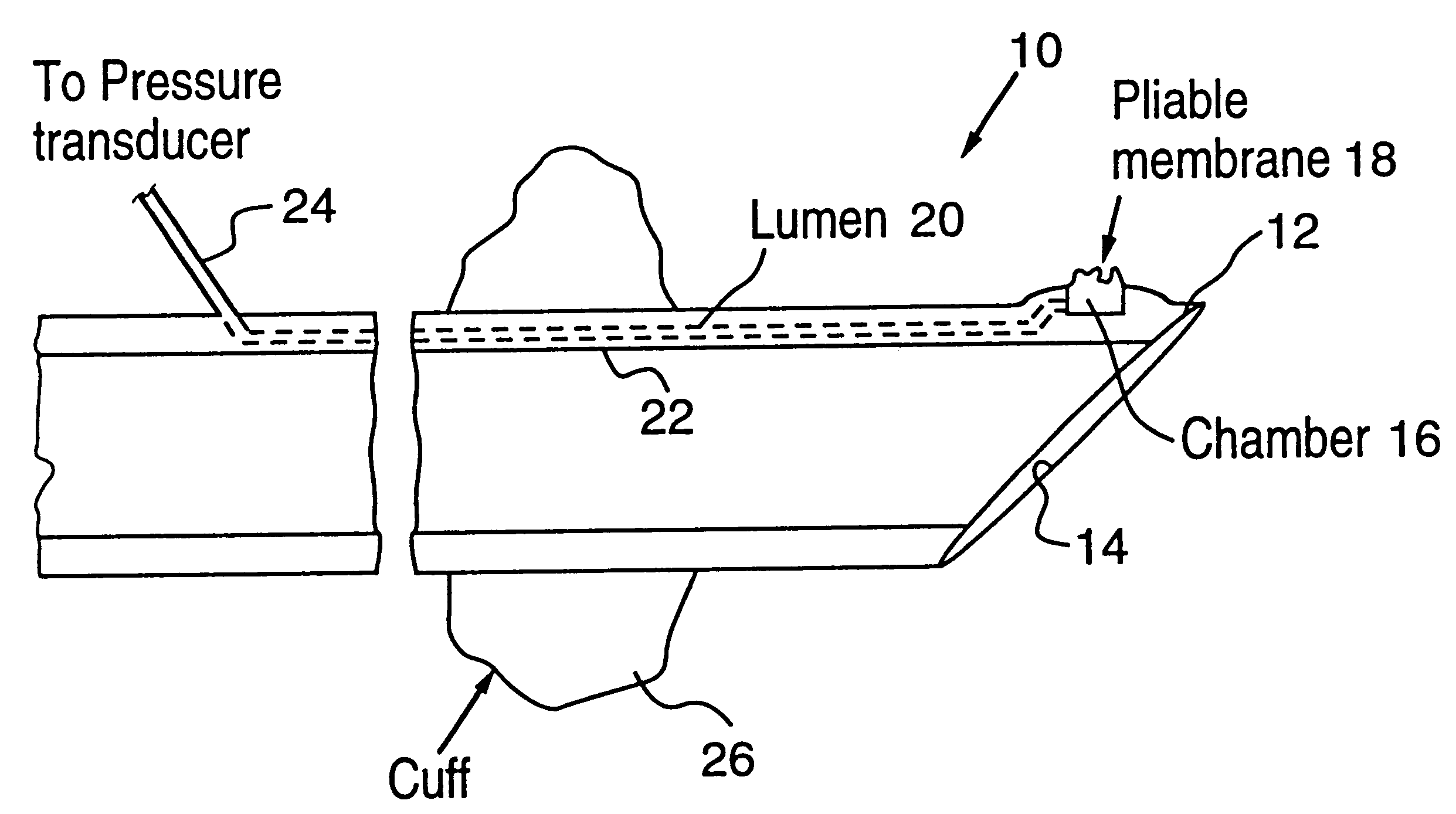
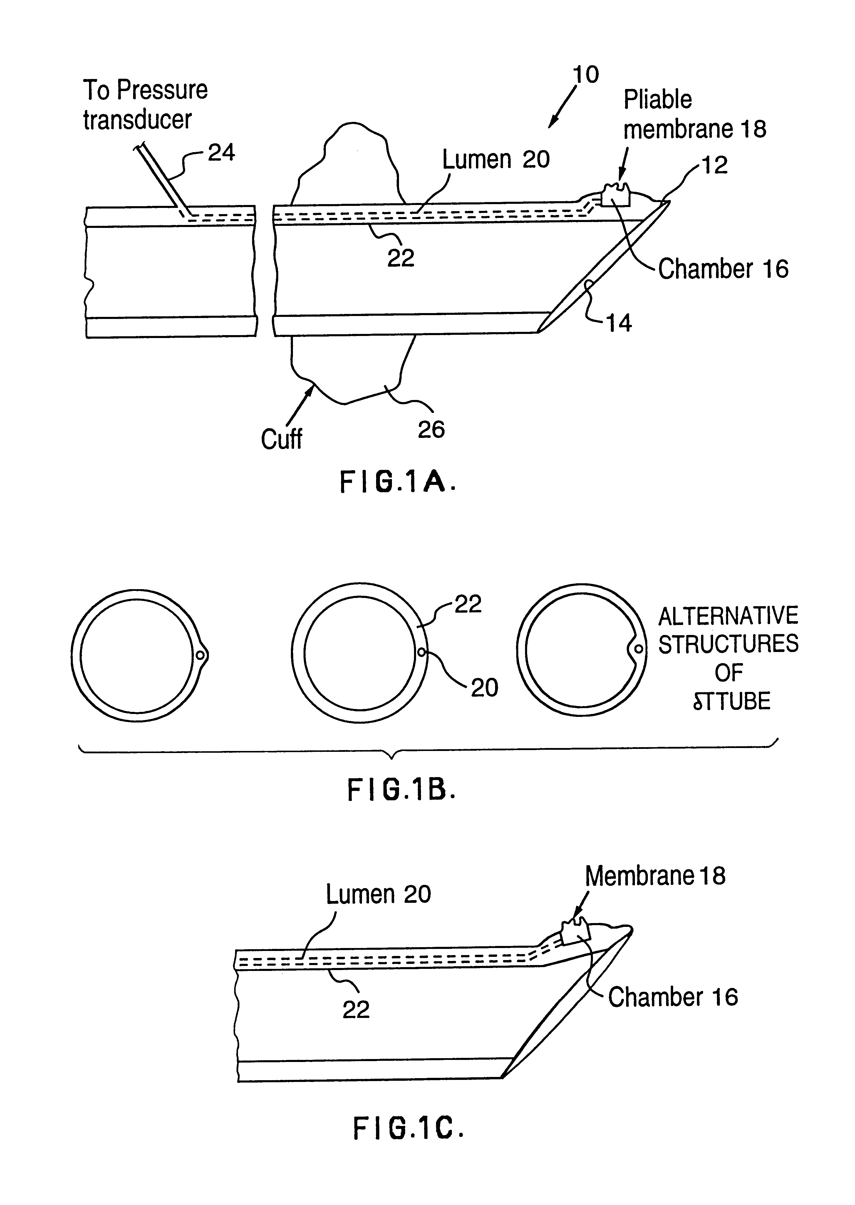
Referring first to FIGS. 1A to 1C, an endotracheal tube 10 is constructed such that the wall thickness near the long end 12 of the slanted orifice 14 is greater than usual in order to accommodate a small chamber 16. The external wall of the chamber is made of highly pliable membrane 18 with some redundancy such that, starting from a collapsed position (membrane 18 abutting on internal wall of chamber 16) about 0.1 ml or more of air can be injected in chamber without development of significant back pressure (e.g. less than about 1 cm H.sub.2 O). A lumen 20 incorporated in the wall 22 of the tube 10, communicates with the chamber 16 and runs along the tube 10 until near the external end where it connects with an external narrow tube or catheter 24 that serves as a conduit to the pressure measuring device (transducer). Three alternate locations for the lumen 20 within the wall 22 of the ET tube are shown in FIG. 1B.

In normal use, the pliable external wall 18 of the chamber 16 normally ...


PUM


Abstract

A endotracheal tube for patient ventilation is modified to permit measurement of pressure at the patient trachea by providing a chamber in the end of the ET tube to be located in the patient, airway. This chamber has a highly pliant external wall with a degree of redundancy and is connected to a pressure measuring device exterior of the patient by a lumen in the wall of the ET tube. In addition, apparatus for controlling airway pressure during exhalation comprises valve means connected via a first inlet to an exhalation tube from a patient airway, connected to a source of negative pressure through an outlet and having a second inlet with a variable flow control means for controlling the flow of gas therethrough. Gas pressure is controlled within the valve by varying the pressure gradient between the upstream and downstream sides of the second inlet so that it equals the pressure gradient between the patient airway and the downstream side of the second inlet.

Description

The present invention relates to modification to patient ventilators of a variety of different types to achieve improved operation.BACKGROUND TO THE INVENTIONDuring mechanical ventilation the pressure at the external end of the endotracheal tube (ET tube) does not accurately reflect the pressure in the patient's trachea because the ET tube possesses a finite resistance which dictates the presence of a gradient between the two ends of the tube in the, presence of flow. During the inhalation phase the external pressure overestimates the pressure in the patient's trachea, the latter being the pressure actually applied to the patient to assist his breathing. In extreme cases, external pressure may be positive, implying that patient is being assisted, while tracheal pressure is negative, whereby the patient's breathing is actually being hindered, rather than assisted, on account of the resistance of the ET tube. Furthermore, because the external pressure during the inhalation phase is ro...

Claims


Application Information

Patent Timeline
Patent Type & Authority Patents(United States)
IPC IPC(8): A61M16/04A61M16/00A61M25/00
CPCA61M16/04A61M16/0463A61M16/0009A61M2016/0021A61M2025/0003
Inventor YOUNES, MAGDY
Owner UNIVERSITY OF MANITOBA
Why Eureka
Try Eureka