

CTI Control System
a control system and control technology, applied in the field of cti technology, can solve the problem that no services can be provided to terminal units connected via a public switching network
Inactive Publication Date: 2004-07-06
FUJITSU LTD
View PDF21 Cites 76 Cited by
- Summary
- Abstract
- Description
- Claims
- Application Information
AI Technical Summary
Benefits of technology
Thus, by setting the information specifying the issue / non-issue of a result notification and the information specifying a monitor time, the CTI control can be executed and the control result can be checked more efficiently and flexibly using the electronic mail.
Thus, by the electronic mail containing exchange information and message information about one or more media, and by specifying using the scenario information the process timing and the process type for the exchange information and the message information about one or more media, a message can be effectively transmitted through simple CTI control via electronic mail.
Thus, according to the present invention, a concrete camp-on service of performing the two-point connection control can be efficiently realized.
Problems solved by technology
However, in the conventional camp-on service, terminal units allowed to receive a service are limited to those connected to the same exchange unit, or to those belonging to a switching network connected via a private line controlled by a No.7 common line signal system, etc., and no services can be provided to terminal units connected via a public switching network such as a public telephone network, a public ISDN network, etc.
Method used
View moreImage
Smart ImageViewing Examples

Examples
Embodiment Construction
The present invention can be designed as a computer-readable storage medium used to direct a computer to perform the same functions realized by each configuration of the CTI server 2 or WS 3 (CTI client) according to the above described preferred embodiment of the present invention.
For example, as shown in FIG. 59, a program for realizing each function according to a preferred embodiment of the present invention is executed after being loaded to memory (RAM or a hard disk, etc.) 5905 in a body 5904 of a computer 5901 forming the CTI server 2 or the WS 3 through a portable storage medium 5902 such as a floppy disk, a CD-ROM disk, an optical disk, a removable hard disk, etc. or through a network line 5903.
Login to View More PUM
 Abstract
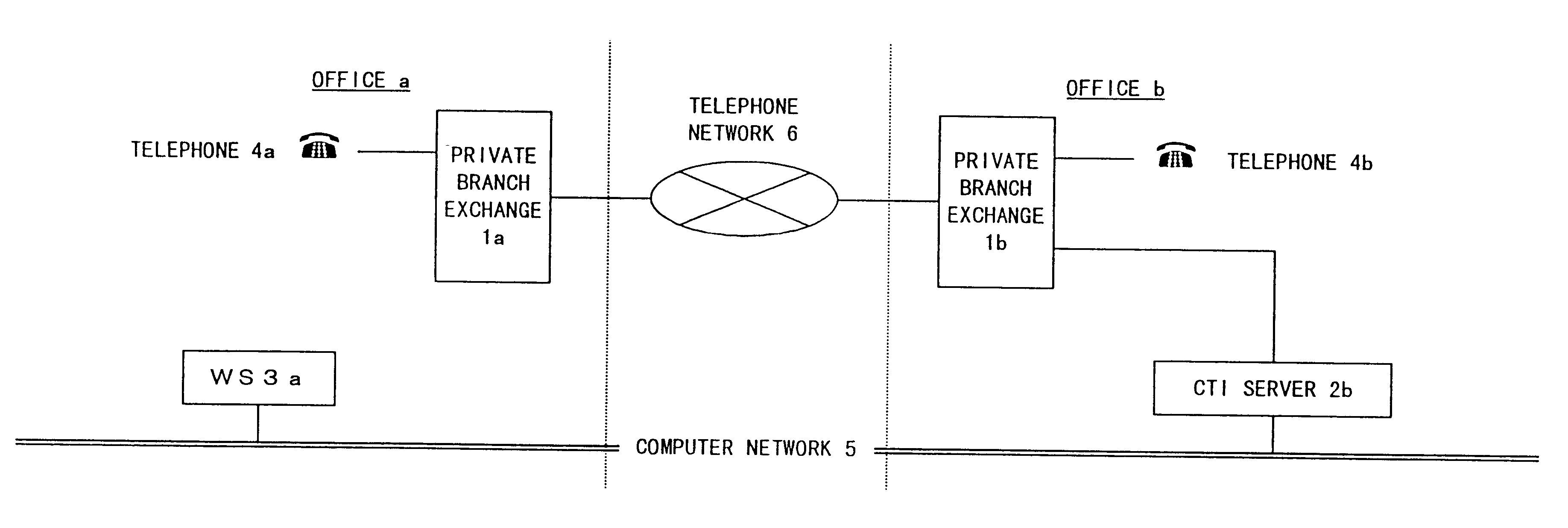
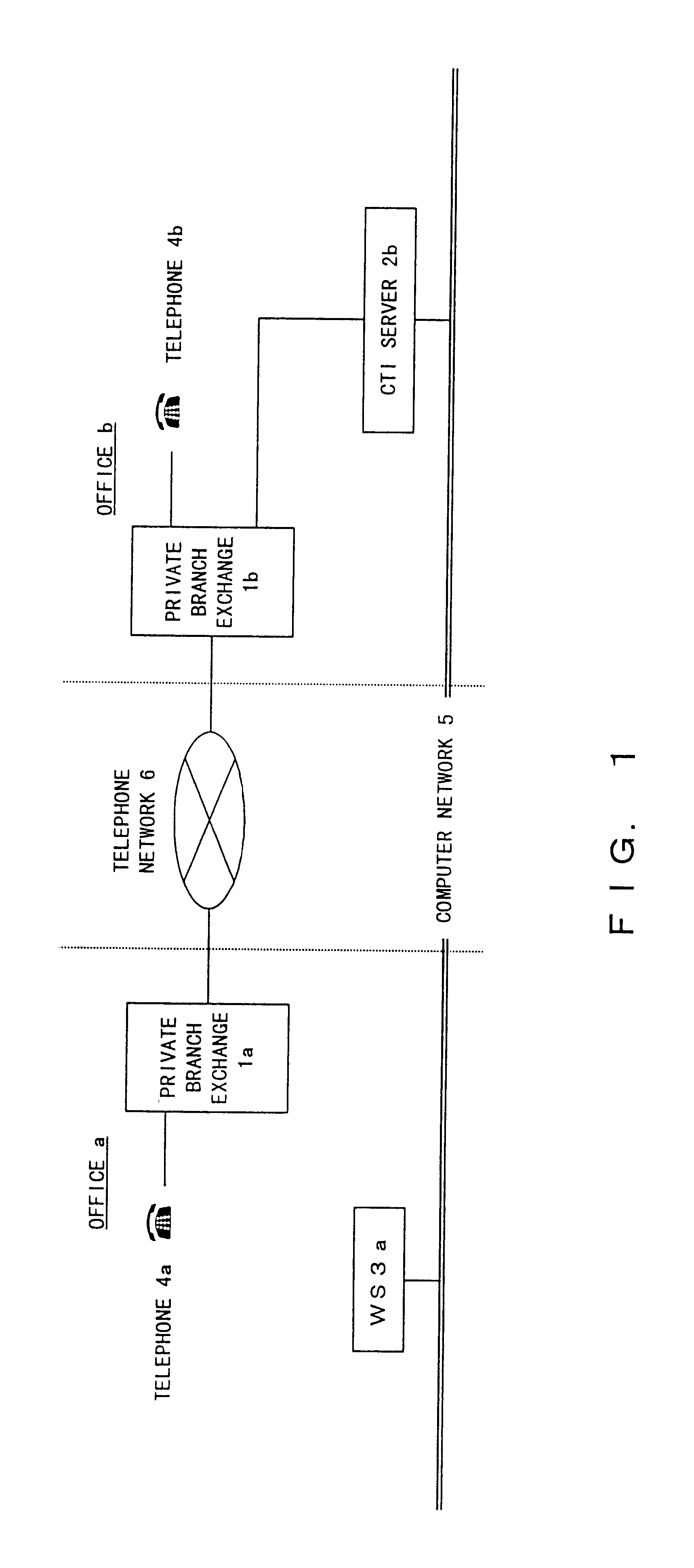
When a telephone a belonging to an office a calls up a telephone b belonging to an office b, a subscriber of the telephone a operates a WS a connected to a computer network and edits camp-on request information when the telephone b is busy. The camp-on request information is transferred from the WS a to a CTI server b belonging to the office b connected to the computer network. The CTI server unit b performs camp-on control between the telephone b belonging to the office b and the telephone a belonging to the office a by controlling a private branch exchange b based on a schedule corresponding to the received camp-on request information.
Description
1. Field of the InventionThe present invention relates to the CTI technology of setting a schedule for line connection through telephone networks.2. Description of the Related ArtWith the growing popularity of the Internet and LANs (Local Area Networks), a media signal of an exchange unit such as a voice / FAX message, etc. conventionally controlled only by an exchange unit, can be communicated between a computer terminal unit and a destination terminal unit (telephone terminal unit, FAX terminal unit, etc.) in a switching network (local area switching network and public switching network) by connecting the computer terminal unit to the exchange unit through a modem and a terminal adapter connected to the computer terminal unit, or through a server unit to which the computer terminal unit is connected in a network.Recently, a technology has been developed to communicate in real time a voice message, etc. between computer terminal units connected to the Internet, a LAN, etc., without s...
Claims
Login to View More Application Information
Patent Timeline
 IPC IPC(8): H04M3/00H04M3/48H04M3/53H04M3/42H04Q3/62H04Q3/545H04L29/10H04M7/00
CPCH04Q2213/13103H04M3/5307H04Q2213/1322H04Q2213/13389H04M2242/16H04M7/006H04Q2213/13173H04Q2213/13152H04Q3/62H04Q2213/13204H04Q2213/13093H04M7/009H04Q2213/13034H04M3/48H04M3/42323
InventorFUKUDA, HISASHIMATSUNE, HIDEAKI
OwnerFUJITSU LTD