Fiber optical polarizer assembly
a fiber optical polarizer and assembly method technology, applied in the direction of optics, instruments, optical light guides, etc., can solve the problems of high cost, unstable arrangement, waste of space,
- Summary
- Abstract
- Description
- Claims
- Application Information
AI Technical Summary
Benefits of technology
Problems solved by technology
Method used
Image

Examples
Embodiment Construction
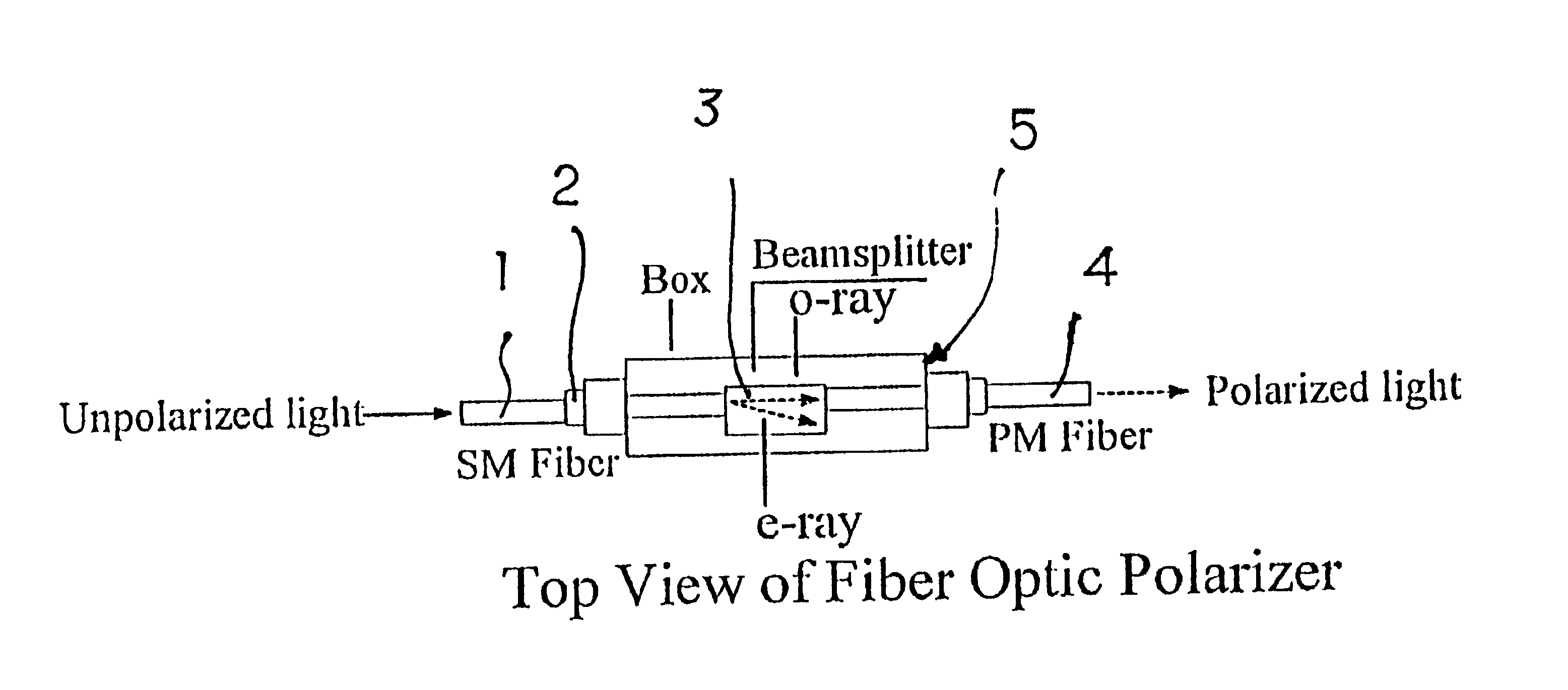
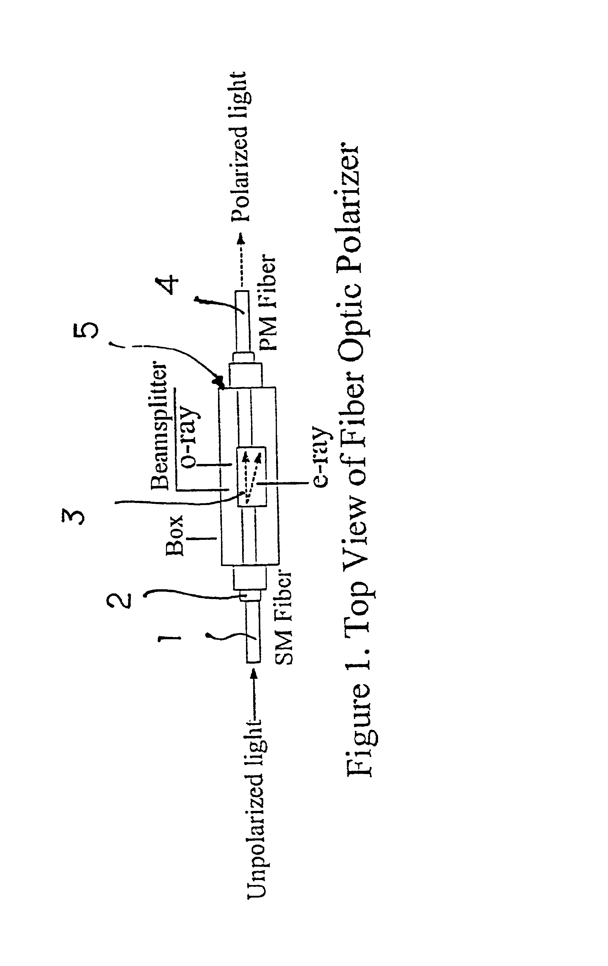
Referring to FIG. 1, the top view of the new fiber optics polarizer comprises of the single mode (SM) fiber 1, the cladding plastic layer 2, the beam splitter 3, the polarization maintaining (PM) fiber 4, the metal or plastic box 5.
From FIG. 1, unpolarized light transmits through the single mode (SM) fiber 1 to be separated into ordinary ray (o-ray) and extraordinary ray (e-ray) by the beam splitter 3. The o-ray is the polarized light to enter the polarization mode (PM) fiber 4 from the beam splitter 3. The box 5 is used to pack the integrated component. The cladding plastic layer 2 is used to protecting the single mode fiber 1 and the polarization maintaining fiber 4.
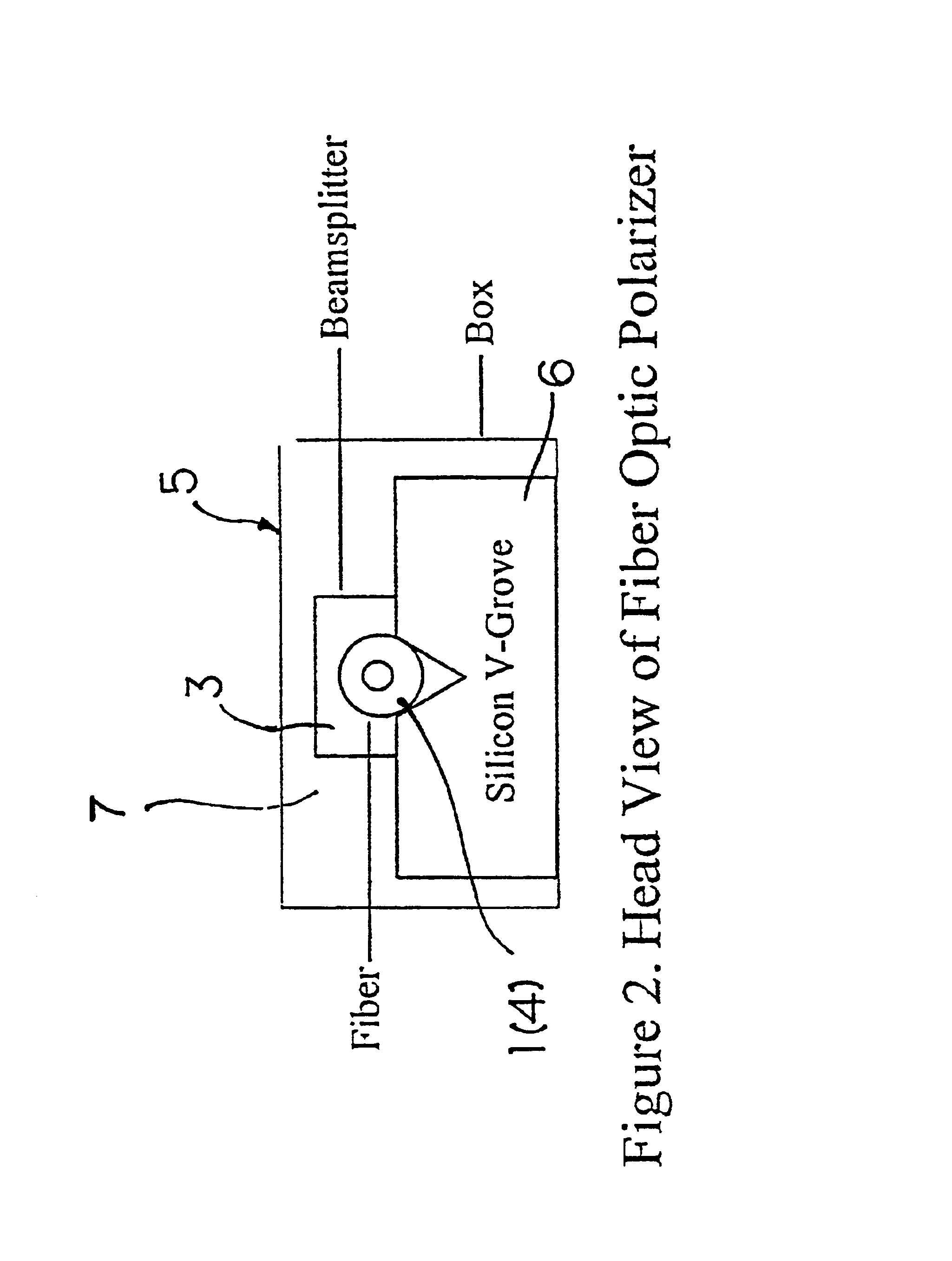
Referring to FIG. 2, the head view of the new fiber optics polarizer comprises of the single mode (SM) fiber 1 or the polarization maintaining fiber 4, the beam splitter 3, the metal or plastic box 5, the silicon V-grove chuck 6.
From FIG. 2, the single mode (SM) fiber 1 or the polarization maintaining fiber 4 is stick ...
PUM
 Abstract
Description
Claims
Application Information
 - R&D
- Intellectual Property
- Life Sciences
- Materials
- Tech Scout
- Unparalleled Data Quality
- Higher Quality Content
- 60% Fewer Hallucinations
Browse by: Latest US Patents, China's latest patents, Technical Efficacy Thesaurus, Application Domain, Technology Topic, Popular Technical Reports.
© 2025 PatSnap. All rights reserved.Legal|Privacy policy|Modern Slavery Act Transparency Statement|Sitemap|About US| Contact US: help@patsnap.com