Multiple input multiplexing connection apparatus and method

a multiplexing connection and input technology, applied in the direction of cables between relatively moving parts, instruments, electric devices, etc., can solve the problems of increasing the number of input devices, and increasing the size of individual wires

Inactive Publication Date: 2004-07-13
METHODE ELETRONICS INC
View PDF2 Cites 11 Cited by
  • Summary
  • Abstract
  • Description
  • Claims
  • Application Information

AI Technical Summary

Benefits of technology

A first object of the present invention is to increase the number of input devices that can be accommodated over a single connection line.
A second object of the present invention is to reduce the manufacturing cost of a connection system.
A third object of the present invention is to reduce the total number of individual wires between multiple input devices and receiving modules in a connection system.
A fourth object of the present invention is to reduce the weight of a connection system.
A fifth object of the present invention is to reduce the complexity of a connection system.
A sixth object of the present invention is to avoid using any microprocessors in a connection system in order to reduce cost and size.

Problems solved by technology

Connection to and from these inputs is creating a huge demand on the design configurations to accommodate the large amount of inputs over limited connections.
Furthermore, the size of individual wires cannot decrease due to the requirements of mechanical strength and durability.
Each additional circuit adds weight and cost due to the additional module interconnect components and wires.
However, the requirements of more sensor circuits, reduced vehicle weight, reduced costs, and reduced free space for components, are adding additional pressure to maximize the number of inputs that can be handled by each connection.
Eventually, however, there will be no more room available to accommodate an ever increasing clockspring.
This area is further challenged by complex suspension controls being added to new car designs, and these suspension controls must share the same location in the steering column as the clockspring in order to function properly, and needed additional space is not available.
While a communication bus can handle a large number of input devices per connector, such a design requires a plurality of microprocessors which makes the system expensive to produce.
A communication bus also utilizes a lot of circuit board space, which makes the system expensive to produce.

Method used


Image

  • Multiple input multiplexing connection apparatus and method
  • Multiple input multiplexing connection apparatus and method
  • Multiple input multiplexing connection apparatus and method

Examples


Embodiment Construction

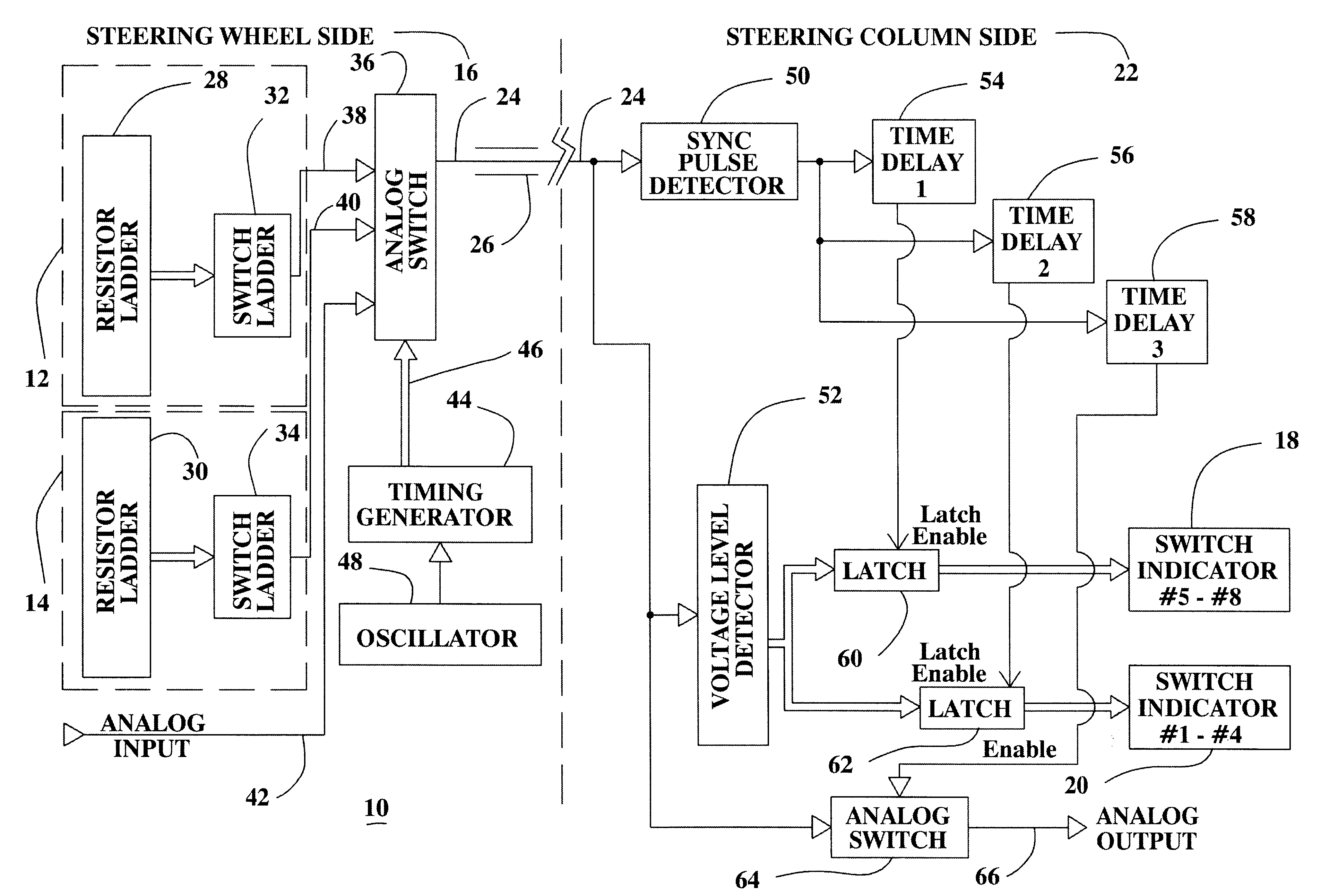
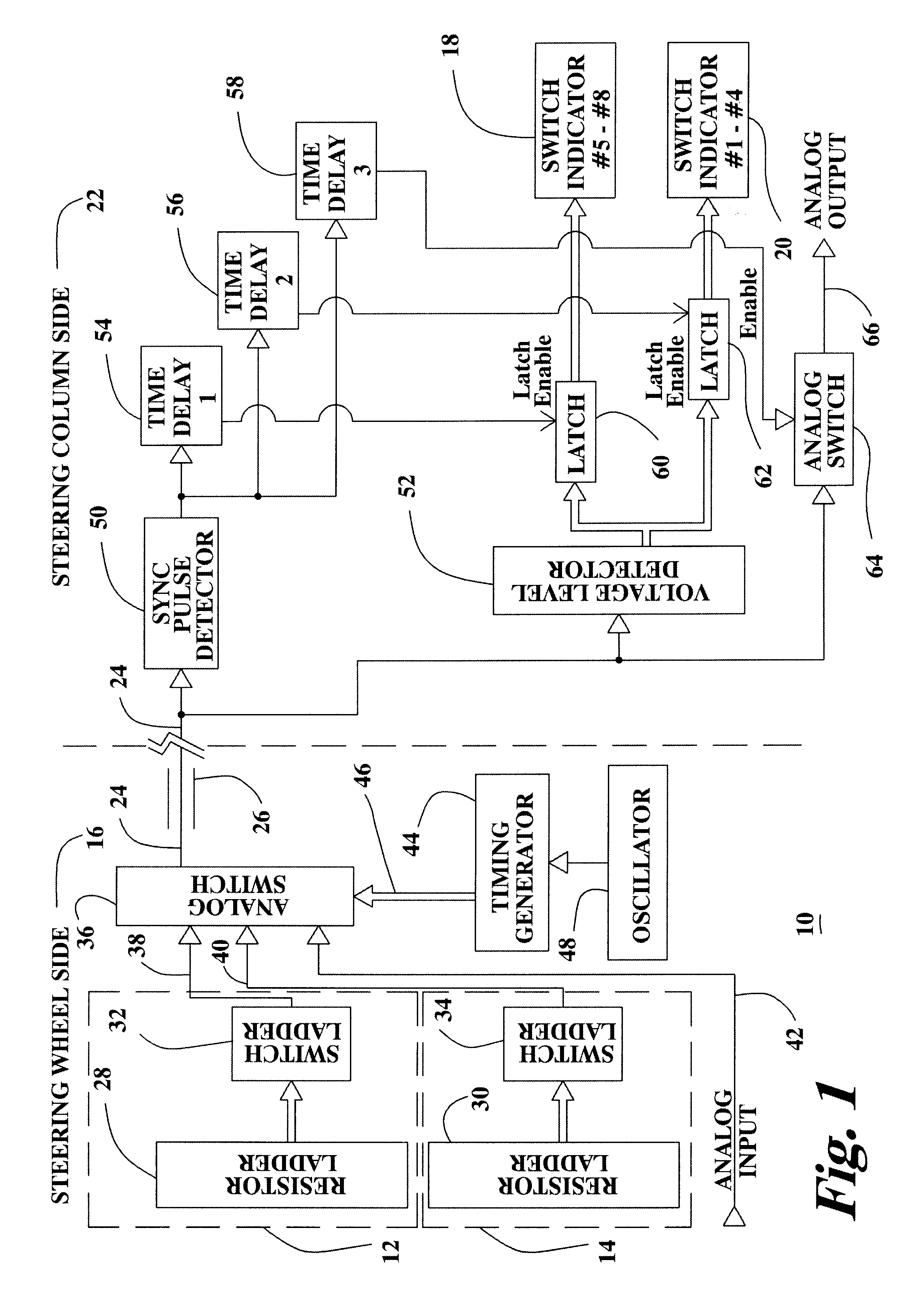
Referring now to the drawings, FIG. 1 illustrates a multiplexing connection system 10 configured in accordance with the present invention. The connection system 10 enables multiple input devices 12,14 on the steering wheel side 16 of a vehicle to communicate with multiple output devices 18,20 on the steering column side 22 of a vehicle via a single wire or line 24. The single wire 24 is typically contained within a clockspring 26 on the steering column that provides an interconnection between the steering wheel side 16 and the steering column side 22 of a vehicle. The clockspring 26 is generally a flat ribbon cable that is wound around the steering column of a vehicle. The clockspring contains multiple, single wires.

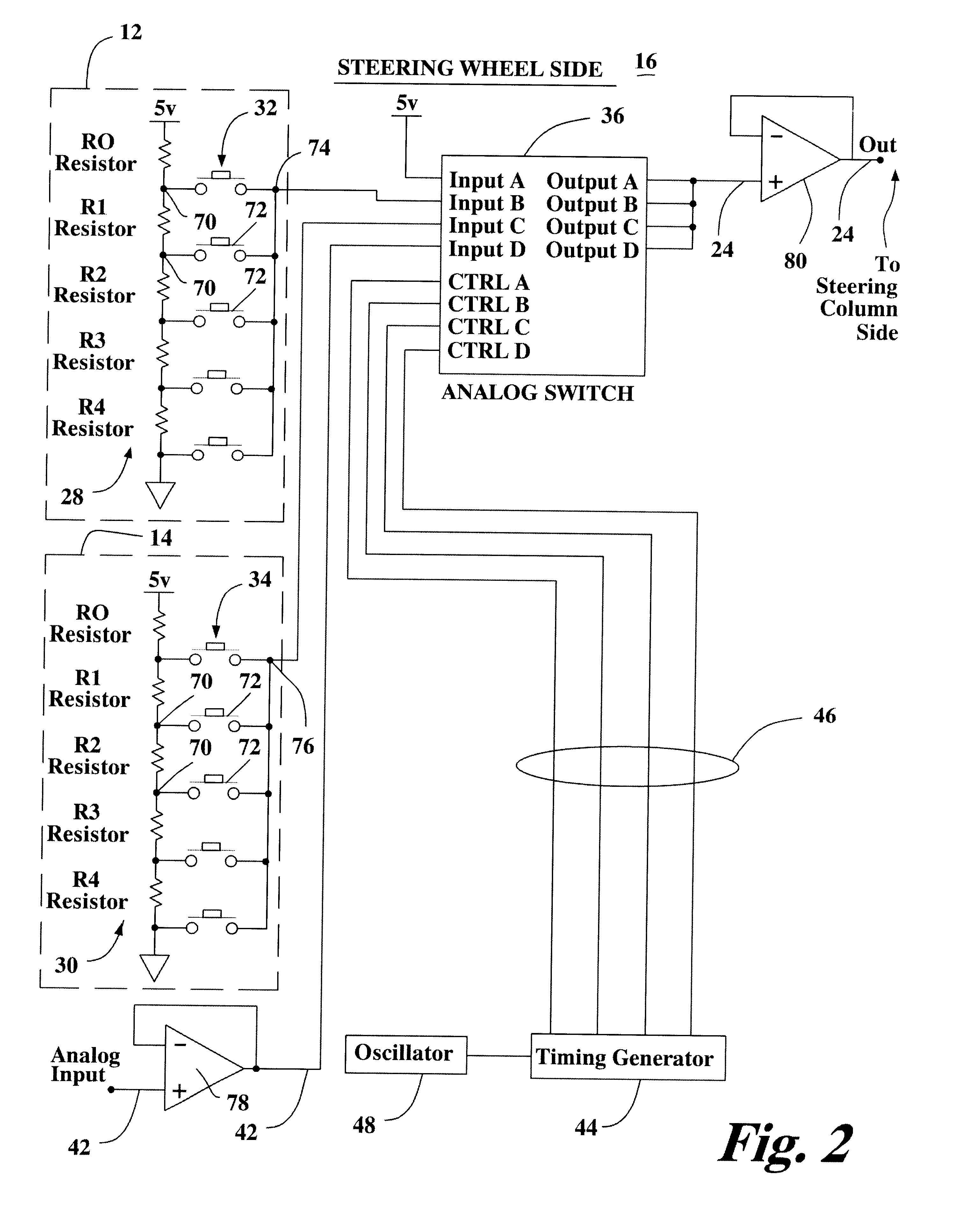
In a preferred embodiment, on the steering wheel side 16 of the connection system 10, each input device 12,14 includes a resistor ladder 28,30 and a switch ladder 32,34. Each switch ladder 32,34 is connected to an analog switch 36 by a single line 38,40, respectively. A ...


PUM


Abstract

A connection system for communicating multiple signals between a steering wheel and a steering column of a vehicle over a single wire is provided that uses time division to multiplex multiple signals. A plurality of signals are multiplexed together ranging from two to as many signals as desired. Input switches are grouped together to form a ladder multiplexer, such as a resistive multiplexer, that includes voltage and current muxing. A plurality of ladder multiplexers are joined together in a time division multiplexing scheme that operates continuously. An analog line may be added as a single channel. A marker pulse is used to signal the start of each time window to be divided for all the channels. Time division multiplexing is provided by a number of switching means.

Description

The present invention relates generally to a connection system between input devices and detector modules. More particularly, the present invention relates to a connection system between input detectors on a vehicle steering wheel and detector modules on a column side of a vehicle steering system.Modern vehicles are requiring more and more user-input functions. These functions include switches for cruise control, radio, tape player, compact disk player, windshield wipers, seat positioning, electric mirrors, heating, ventilation, air conditioning, and rear window defogger, just to name a few. Many of these functions are located on switch pods or in the steering wheel. Typically the input is in digital form to provide high-resolution and simplicity. Even microphones and speakers are becoming a desired feature for phone usage. Connection to and from these inputs is creating a huge demand on the design configurations to accommodate the large amount of inputs over limited connections.Wir...

Claims


Application Information

Patent Timeline
Patent Type & Authority Patents(United States)
IPC IPC(8): B60R16/02B60R16/027B60R16/03
CPCB60R16/027B60R16/0315
Inventor WAND, THOMAS J.
Owner METHODE ELETRONICS INC
Why Eureka
Try Eureka