Catalyst state detector for exhaust gas purifying catalyst

a technology of purifying catalyst and catalyst state, which is applied in the direction of exhaust treatment electric control, separation process, instruments, etc., can solve the problems of deterioration of adsorbent capacity, deterioration of adsorbent pores, and gradual deterioration of adsorbent ability, etc., and achieves accurate detection of a state and is manufactured at a low price

Inactive Publication Date: 2004-07-20
HONDA MOTOR CO LTD
View PDF11 Cites 10 Cited by
  • Summary
  • Abstract
  • Description
  • Claims
  • Application Information

AI Technical Summary

Benefits of technology

The present invention has been made to solve the problems as mentioned above, and its object is to provide a catalyst state detector for an exhaust gas purifying catalyst, which is capable of accurately detecting a state of an adsorbent of the exhaust gas purifying catalyst for adsorbing hydrocarbons, including deterioration, and which can be manufactured at a low price.
According to this preferred embodiment of the catalyst state detector, since the adsorbent includes zeolite, it is possible to provide an adsorbent which is highly heat resistant and also invulnerable to deterioration, as compared with, for example, silica gel, active carbon, or the like used as an adsorbent. In addition, such an adsorbent can properly adsorb hydrocarbons in exhaust gases at low temperatures at the start of the internal combustion engine. Also, the adsorbent comprised of zeolite can desorb hydrocarbons once adsorbed thereby at high temperatures without fail. Further, since zeolite exhibits a significantly high correlation of adsorption characteristics for hydrocarbons and moisture, it is possible to improve the accuracy in the detection of deterioration of the adsorbent by the catalyst state detector for an exhaust gas purifying catalyst which acts as a deterioration detector.

Problems solved by technology

However, for approximately 30 to 40 seconds after the cold start of the engine, the temperature of the three-way catalyst is lower than the predetermined temperature, and the catalyst remains inactive, so that among the harmful substance, particularly hydrocarbons are emitted from the engine as they are as unburned combustible components.
As described above, while adsorption and desorption of hydrocarbons are repeated in the adsorbent, the amount of undesorbed hydrocarbons remaining in the adsorbent may gradually increase or cause destruction of pores of the adsorbent during a long-term use of the adsorbent.
As a result, the adsorbent is deteriorated, i.e., experiences a gradually deteriorated capability of adsorbing hydrocarbons.
The foregoing detecting methods suffer from the following problems, respectively.
In the method (1) relying on a hydrocarbon sensor, a generally employed hydrocarbon sensor is limited to detection of the concentration of a particular hydrocarbon (one kind of hydrocarbon having a predetermined number of carbons), so that it is difficult to accurately detect as a whole the concentrations of various hydrocarbons respectively having different numbers of carbons by such a hydrocarbon sensor.
It is further difficult to correctly detect the deterioration of the adsorbent based on the result of the detection.
In addition, the hydrocarbon sensor itself is quite expensive as compared with other sensors.
In the method (2) relying on temperature sensors, on the other hand, the deterioration of the adsorbent is indirectly detected by detecting temperatures of exhaust gases at two different locations, causing a susceptibility to an error in the detection of deterioration and a low detection accuracy.
In addition, temperature sensors are expensive as is the case of the hydrocarbon sensor, and the use of two temperature sensors further results in a higher cost of the exhaust system as a whole.

Method used


Image

  • Catalyst state detector for exhaust gas purifying catalyst
  • Catalyst state detector for exhaust gas purifying catalyst
  • Catalyst state detector for exhaust gas purifying catalyst

Examples


first embodiment

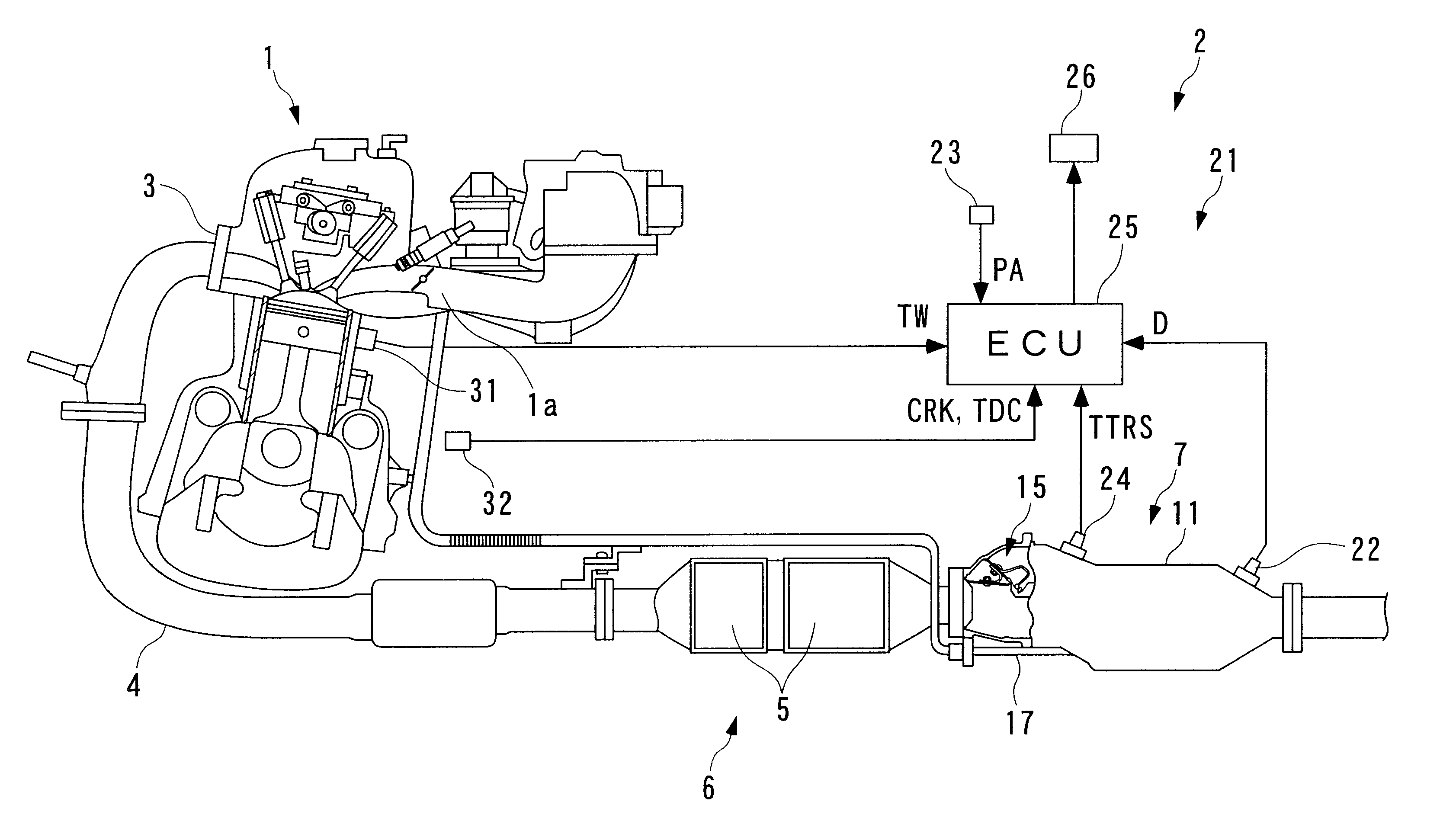
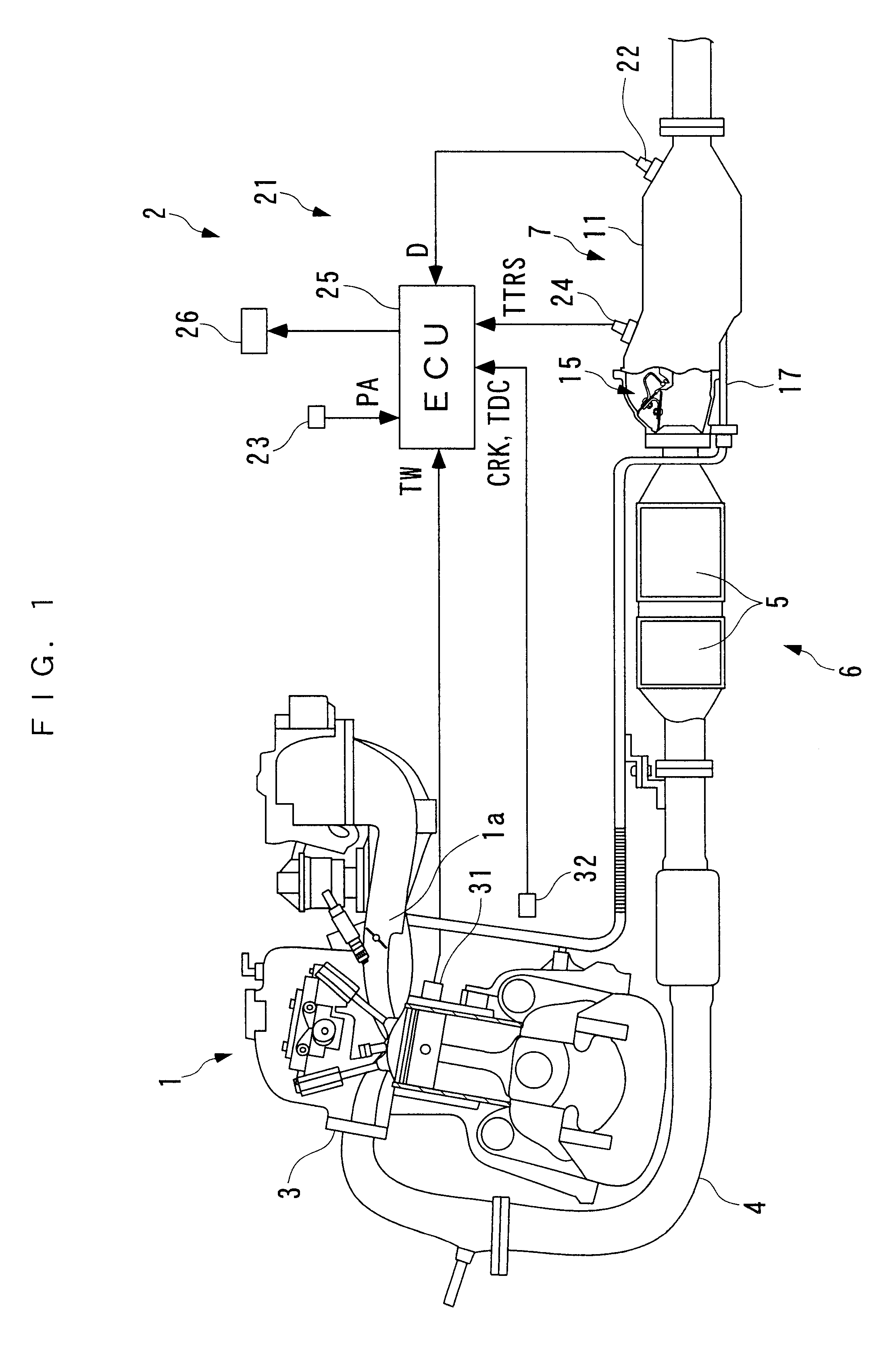
In the following, preferred embodiments of the present invention will be described in detail with reference to the accompanying drawings. FIG. 1 illustrates an internal combustion engine in which a catalyst state detector for an exhaust gas purifying catalyst according to the present invention is applied as an adsorbent deterioration detector. This internal combustion engine 1 (hereinafter simply referred to as the "engine") includes an exhaust system 2 which is configured to emit exhaust gases emitted from the engine 1 to the outside (atmosphere) while purifying the same, and recirculate a portion of the exhaust gases to the engine 1 (EGR). The exhaust system 2 has an exhaust pipe 4 connected to the engine 1 through an exhaust manifold 3.

The exhaust system 2 is also provided, at intermediate locations of the exhaust pipe 4, with an catalyzer 6 having two three-way catalysts 5 as an exhaust gas purifying catalyst for purifying exhaust gases, and a hydrocarbon adsorbent catalyzer 7 f...

second embodiment

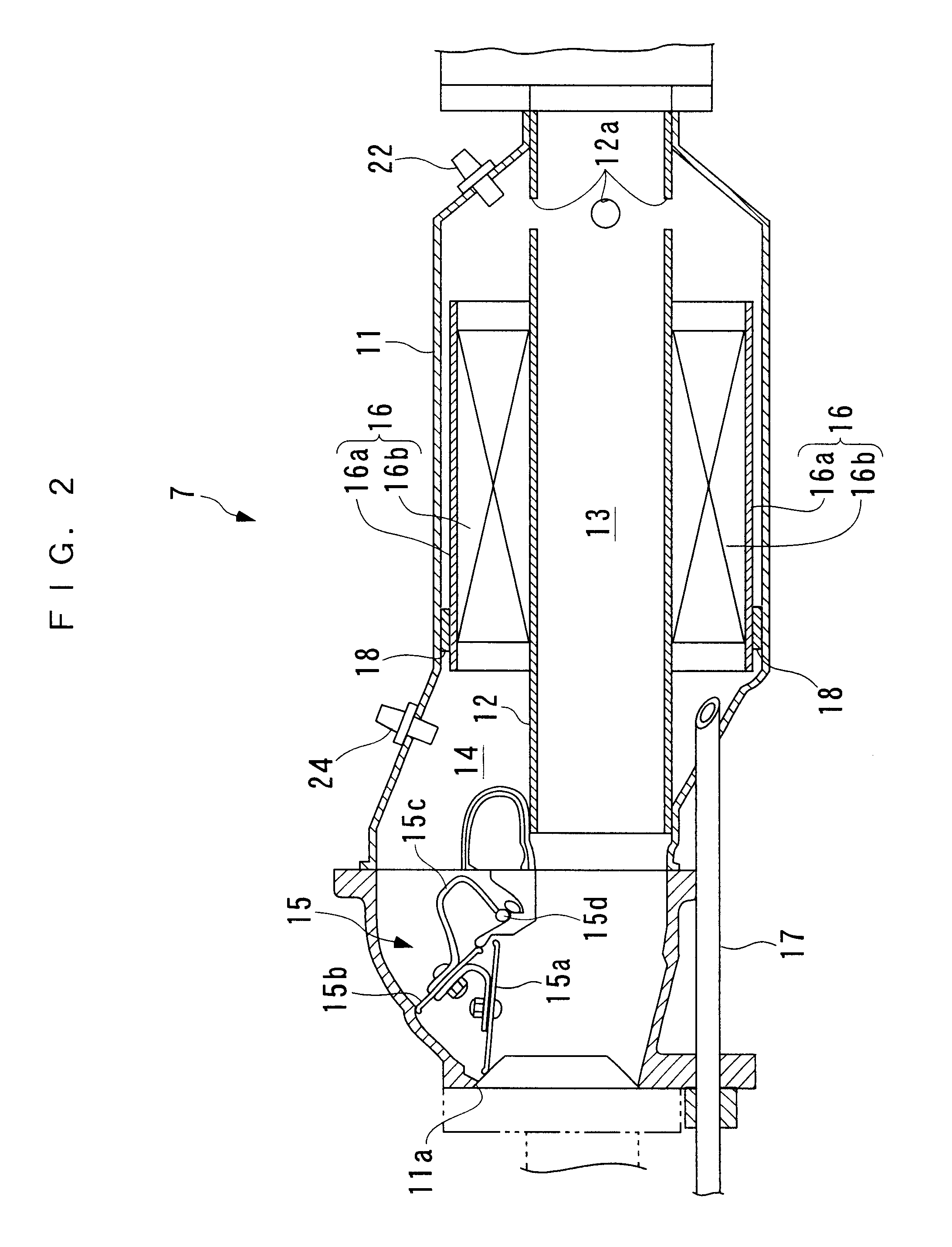
As described above in detail, by detecting the downstream humidity which has a high correlation to an actual adsorbed state of hydrocarbons in the HC adsorbent 16, it is possible to accurately detect an adsorbed state and a desorbed state of hydrocarbons in the HC adsorbent 16. Also, by compensating the humidity sensor 22 for a response delay, it is possible to correctly detect the state of the HC adsorbent 16 even with the humidity sensor 22 which exhibits a low responsibility, while properly compensating such the humidity sensor 22 for the response delay. Further, by heating the sensor element 22a of the humidity sensor 22 by the heater 28 in accordance with an operating state of the engine 1, it is possible to bring the sensor element 22a into a state suitable for detecting the humidity. As a result, the humidity can be correctly detected while avoiding inconveniences, for example, dew condensation on the sensor element 22a, coke deposition on the sensor element 22a, and so on.

I...


PUM

PropertyMeasurementUnit
temperatureaaaaaaaaaa

Abstract

A catalyst state detector for detecting a state of an exhaust gas purifying catalyst which is capable of accurately detecting the state, including deterioration, of an HC adsorbent contained in the exhaust gas purifying catalyst for adsorbing hydrocarbons in exhaust gases of an internal combustion engine, and can be manufactured at a low cost. The exhaust gas purifying catalyst is arranged at an intermediate portion of an exhaust pipe, and the HC adsorbent is capable of adsorbing hydrocarbons and moisture in exhaust gases. The catalyst state detector comprises a downstream humidity sensor arranged at a location downstream of the HC adsorbent in the exhaust pipe for detecting a humidity of the exhaust gases, and an adsorbent state detecting unit (ECU) for detecting the state of the HC adsorbent in accordance with the result of detection made by the downstream humidity sensor.

Description

1. Field of the InventionThe present invention relates to a catalyst state detector for an exhaust gas purifying catalyst which purifies exhaust gases emitted from an internal combustion engine, and more particularly, to a catalyst state detector for an exhaust gas purifying catalyst which purifies exhaust gases using an adsorbent for adsorbing hydrocarbons in exhaust gases.2. Description of the Prior ArtGenerally, in an exhaust system of a gasoline engine or the like, a three-way catalyst is arranged in an intermediate portion of an exhaust pipe in order to purify harmful substances (hydrocarbons, carbon monoxide and nitrogen compounds) in exhaust gases, the amount of which cannot be reduced sufficiently by engine modifications or EGR (exhaust gas recirculation). The three-way catalyst is heated by exhaust gases or by using additional means, and activated at temperatures equal to or higher than a predetermined temperature (300.degree. C., for example), thereby purifying harmful sub...

Claims


Application Information

Patent Timeline
Patent Type & Authority Patents(United States)
IPC IPC(8): F01N11/00F01N3/08F01N7/02F01N7/00G01N33/00B01D53/86F01N3/00F01N3/18F01N3/24F01N13/02F02D35/00F02D45/00
CPCF01N3/0814F01N3/0835F01N3/0878F01N3/101F01N11/00F01N13/0093F01N13/009F01N2250/12F01N2550/03F01N2560/028F01N2570/12F01N2900/0422Y02T10/47Y02T10/22Y02T10/12Y02T10/40
Inventor UENO, MASAKIAKAZAKI, SHUSUKESATO, MASAHIROYAMAZAKI, HIDEHARUENDO, TETSUOIWAKI, YOSHIHISAHAGA, TAKASHISATO, TADASHI
Owner HONDA MOTOR CO LTD
Why Eureka
Try Eureka