Method of electrically blowing fuses under control of an on-chip tester interface apparatus

a technology of electrical blowing and tester interface, which is applied in the field of on-chip fuse controller, can solve the problems of limiting the development and reuse of yesterday's technology, the inability of metal fuses to scale with device technology, and the complicated physical design methodology

Inactive Publication Date: 2004-07-27
MARVELL ASIA PTE LTD
View PDF2 Cites 89 Cited by
  • Summary
  • Abstract
  • Description
  • Claims
  • Application Information

AI Technical Summary

Problems solved by technology

As technology advances, new process and design techniques extend our possibilities while simultaneously limiting the development and reuse of yesterday's technology.
Metal fuses cannot scale with device technology because of the size requirements needed to mechanically program fuses.
Metal fuses also require a direct "line-of-sight" for laser access, which complicates the physical design methodology, since fuses may not be placed underneath overlying power busses.
There is an additional factor further complicating this dilemma: as devices decrease in size, it becomes possible to put more devices onto silicon, leading to smaller chips with larger memory arrays that require more fuses to repair defects.
The area penalty of metal fuses is now more costly than ever.
The customization, test and repair of complex chips in an automated manufacturing test environment with many unique ASIC designs are challenging problems.
This has helped reduce the penalty for using metal fuses, but has not eliminated the problem.

Method used


Image

  • Method of electrically blowing fuses under control of an on-chip tester interface apparatus
  • Method of electrically blowing fuses under control of an on-chip tester interface apparatus
  • Method of electrically blowing fuses under control of an on-chip tester interface apparatus

Examples


Embodiment Construction

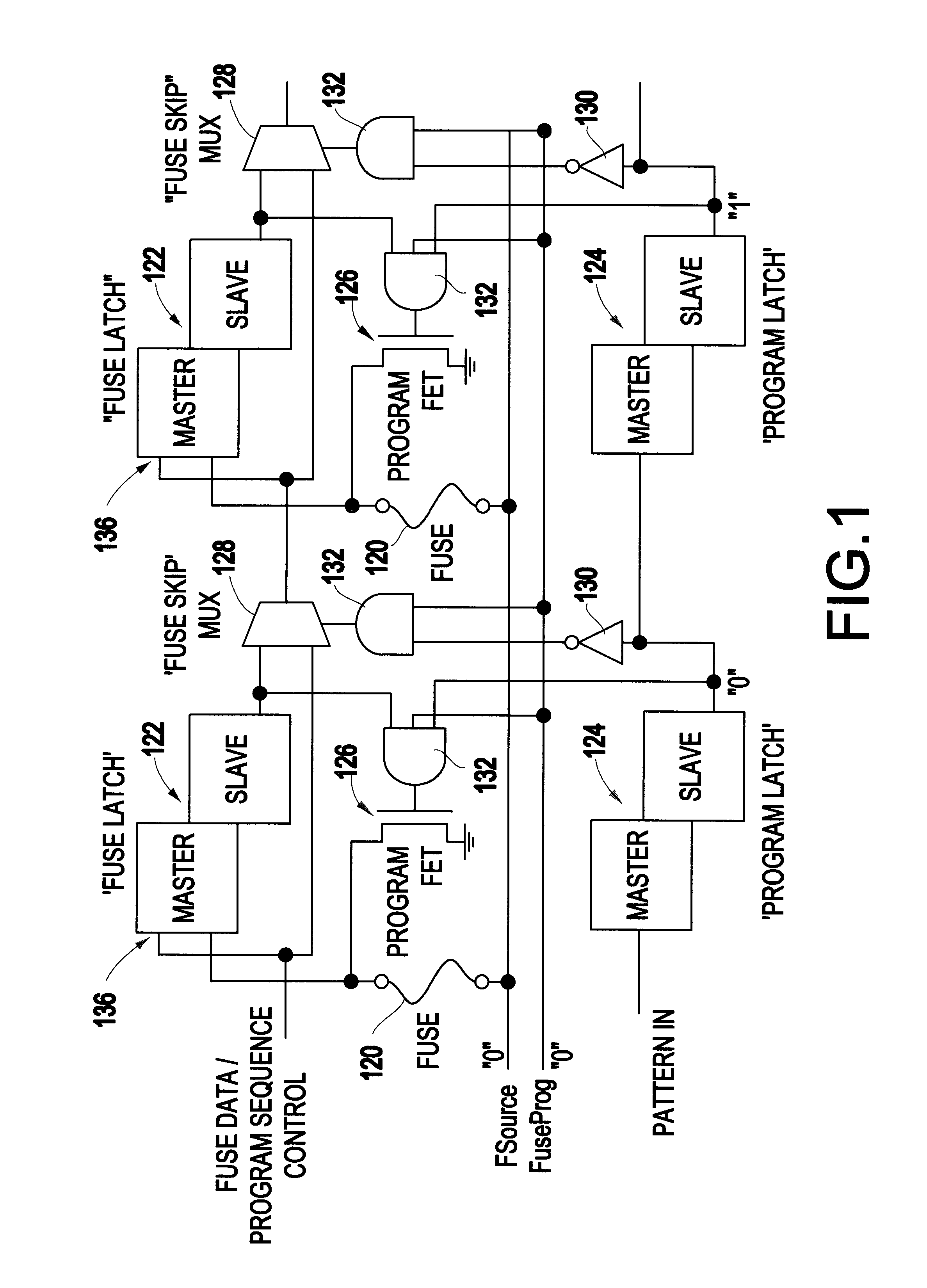
One element enabling on-chip self repair is the electrically-programmed fuse (e-fuse). The e-fuse can best be viewed as an electronically programmed read-only bit. The e-fuse shown in FIG. 1 includes several components: the polysilicon fuse 120, a fuse latch 122, a program latch 124, a program field effect transistor (FET) 126, a look-ahead programming multiplexor (mux) 128, an inverter 130, and AND circuits 132.

The fuse 120 has two possible logic states. It can remain intact where its value is evaluated as a logical `zero`. The other state is "programmed" (e.g., blown, opened, etc.) and evaluates to a logical `one` in this example. For example, a direct current (DC) pulse of 10 mA in amplitude and duration of 200 us can program the fuse 120. This relatively high current programs the fuse by dramatically increasing the resistance of the polysilicon link 120. This method of programming poses additional challenges with respect to delivering the current necessary to program each fuse. ...


PUM


Abstract

A chip repair system designed for automated test equipment independent application on many unique very dense ASIC devices in a high turnover environment is disclosed. During test, the system will control on chip built-in self-test (BIST) engines collect and compress repair data, program fuses and finally decompress and reload the repair data for post fuse testing. In end use application this system decompresses and loads the repair data at power-up or at the request of the system.

Description

1. Field of the InventionThe present invention generally relates to testing and replacing defective devices through the use of fuses and more specifically to an on-chip fuse controller that provides a uniform interface for tester access across multiple chip designs.2. Description of the Related ArtAs technology advances, new process and design techniques extend our possibilities while simultaneously limiting the development and reuse of yesterday's technology. This is the case for fuses. Historically, metal fuses were used for the storage of customization data and repair solutions of defects on silicon chips. Metal fuses required little area relative to devices and could be mechanically programmed with a laser. Today, the area required by metal fuses is significantly greater than the area consumed by the decreasing size of devices. Metal fuses cannot scale with device technology because of the size requirements needed to mechanically program fuses. Metal fuses also require a direct ...

Claims


Application Information

Patent Timeline
Patent Type & Authority Patents(United States)
IPC IPC(8): G11C29/56G11C29/00
CPCG11C29/027G11C29/56G11C17/18G11C29/785G11C2029/1208
Inventor ANAND, DARREN L.COWAN, BRUCEFARNSWORTH, III, L. OWENGILLIS, PAMELA S.JAKOBSEN, PETER O.MONDAL, KRISHNENDUOAKLAND, STEVEN F.OUELLETTE, MICHAEL R.WHEATER, DONALD L.
Owner MARVELL ASIA PTE LTD
Why Eureka
Try Eureka