Light emitting diode

a technology of light-emitting diodes and diodes, which is applied in the direction of basic electric elements, electrical equipment, semiconductor devices, etc., can solve the problem of not being able to produce uniform, bright illumination

Inactive Publication Date: 2004-08-10
CITIZEN ELECTRONICS CO LTD
View PDF2 Cites 33 Cited by
  • Summary
  • Abstract
  • Description
  • Claims
  • Application Information

AI Technical Summary

Benefits of technology

As the light scattering particles 7 fine particles of materials with high reflectivity, such as silicon dioxide (SiO.sub.2) and titanium dioxide (TiO.sub.2), may be advantageously used. The size of individual light scattering particles 7, though not limited to any particular value, may preferably be set to about 1 .mu.m in average diameter in terms of the reflection effect and the ease of handling.
A method of forming the light scattering layer 30 may, for example, involve printing the light projecting surface 27 of the resin sealant 26 with a paint, which has an appropriate amount of light scattering particles 7 dispersed evenly in a paint material, and then curing the printed layer. This method allows the light scattering layer 30 to be formed easily and its thickness to be adjusted with ease. The light scattering is determined by the diameter and the amount of light scattering particles 7 mixed in the paint material. That is, the light scattering action is enhanced by increasing the density of the mixed light scattering particles 7. However, too much of the light scattering particles 7 results in a reduction in transmissivity of the resin sealant 26 and thus an appropriate balance needs to be considered. The thickness of the light scattering layer 30 is determined by a thickness of the printed film. Though not limited to any particular value, the thickness of the light scattering layer 30 may preferably be set to 10-20% of the overall thickness of the resin sealant 26, in which case the light scattering is most effective.

Problems solved by technology

It is therefore not possible to produce a uniform, bright illumination in a wide range of angle.

Method used


Image

  • Light emitting diode
  • Light emitting diode
  • Light emitting diode

Examples


Embodiment Construction

Now, light emitting diodes embodying the present invention will be described in detail by referring to the accompanying drawings.

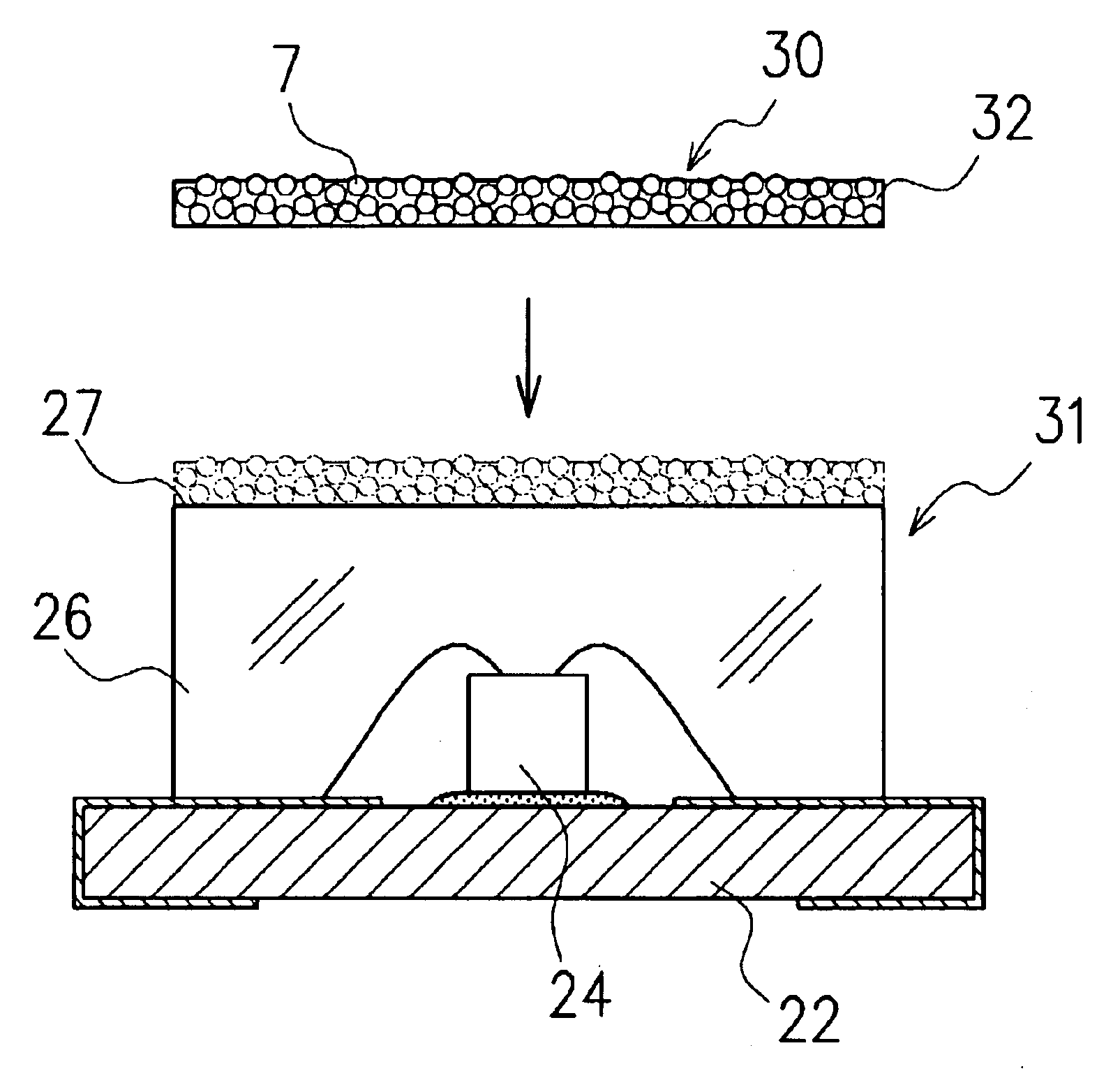
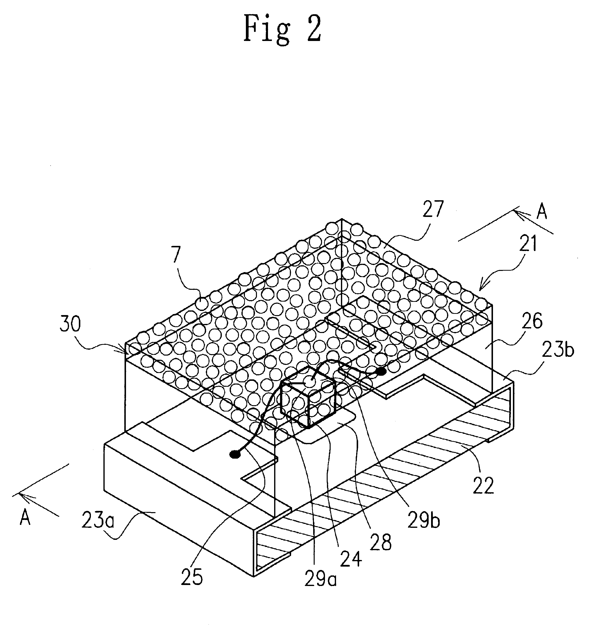
FIG. 2 and FIG. 3 show one embodiment of a light emitting diode according to this invention. The light emitting diode 21 has a substrate 22 made of a glass epoxy resin or BT (Bismaleimide Triazine) resin, a pair of electrodes 23a, 23b attached to the substrate 22, a light emitting element 24 mounted on the substrate 22, bonding wires 25 for electrically connecting the light emitting element 24 to the electrodes 23a, 23b, a resin sealant 26 for sealing the light emitting element 24, the bonding wires 25 and also connecting portions between the electrodes 23a, 23b and the bonding wires 25, and a light scattering layer 30 formed on an outermost layer of the resin sealant 26.

The electrodes 23a, 23b may be mounted on an external substrate such as a mother board not shown.

The light emitting element 24 is formed of, for example, a small cubic silicon chip. The li...


PUM


Abstract

A light emitting diode is disclosed which can enhance the scattering of light produced by a light emitting element to improve a brightness not only at an upper surface but also at side surfaces of a resin sealant covering the light emitting element, thereby providing a high brightness level in a wider range of angle.This light emitting diode comprises a substrate 22, a pair of electrodes 23a, 23b provided on the substrate, a light emitting element 24 mounted on the substrate and electrically connected to the electrodes, a sealant 26 provided on the substrate to seal the electrodes 23a, 23b and the light emitting element 24; and a light scattering layer 30 formed on an outermost layer of a light projecting surface 27 of the sealant 26.

Description

1. Field of the InventionThe present invention relates to a light emitting diode and more particularly to a light emitting diode which enhances a scattering of light produced by a light emitting element to produce a uniform, bright illumination in a wide range of angle.2. Description of the Prior ArtAn example of a known conventional light emitting diode is shown in FIG. 1 (see Japanese Patent Disclosure No. 2000-124507). This light emitting diode 1 includes a substrate 2, a pair of electrodes 3a, 3b formed on both sides of the substrate 2, a light emitting element 4 disposed on the substrate 2, bonding wires 5 electrically connecting the light emitting element 4 to the paired electrodes 3a, 3b, and a resin sealant 6 provided on the substrate 2 to seal the light emitting element 4 and the bonding wires 5. Small light scattering particles 7 are dispersed in the entire resin sealant 6 to scatter light and thereby increase the brightness of light produced.The light emitting diode 1 con...

Claims


Application Information

Patent Timeline
Patent Type & Authority Patents(United States)
IPC IPC(8): H01L33/00H01L33/56H01L33/62
CPCH01L33/44H01L2933/0091H01L2224/48091H01L2224/73265H01L2924/00014
Inventor IMAI, SADATO
Owner CITIZEN ELECTRONICS CO LTD
Why Eureka
Try Eureka