Quiet central vacuum power unit

a central vacuum and power unit technology, applied in the direction of cleaning process and apparatus, vehicle maintenance, application, etc., can solve the problems of silencer not producing a sufficient amount, noise generated by said power unit, and substantial noise emitted outside the central vacuum power uni

Inactive Publication Date: 2004-08-24
NUERA SOLUTIONS AIR NUERA AIR SOLUTIONS
View PDF72 Cites 51 Cited by
  • Summary
  • Abstract
  • Description
  • Claims
  • Application Information

AI Technical Summary

Benefits of technology

Preferably, a sleeve of resilient vibration absorbing material is mounted around the second opening of the second plate. Said sleeve may have an interior of such size and orientation to allow a free axial sliding of said portion of the piping passing across the second opening of said second plate while substantially preventing leak of working air and noise from the acoustic dampening chamber. Advantageously, said sleeve may be mounted on an upper side of said second plate. More preferably, said sleeve is mounted by gluing.

Problems solved by technology

However, said power unit generates high levels of noise.
Two problems arise in the prior art:
The use of a straight silencer fails to generate a sufficient amount of reflexion of said noise against a sound absorbing material and therefore a substantial level of noise is still emitted outside the central vacuum power unit.
The positioning of an elbow outside a canister of said central vacuum power unit creates an abrupt change in air direction that generates noise that is transmitted throught the sidewall of the elbow.
Especially, when a tangential fan is used, the level of noise generated in the area of the elbow is important.
It is to be noted that to seal leaks of noise originating from the opening around the working air exhaust, it is not possible to have a seal having at once no noises leaks and substantial surface properties (to block the noise) while remaining flexible.
Indeed, it was noted that even a very small opening will let considerable amount of noise escaping from the canister.
Also, any vertical movement of the motor-fan assembly due to the vacuum underneath said assembly, contribute to increase the risk of having a solid contact with a structural part of the power unit to thereby transmit vibrations to said structure and generate additional noises (i.e. sound moves through the structure of the canister toward the outside)
They will let substantial amount of noise to propagate across its sidewall.

Method used


Image

  • Quiet central vacuum power unit
  • Quiet central vacuum power unit
  • Quiet central vacuum power unit

Examples


Embodiment Construction

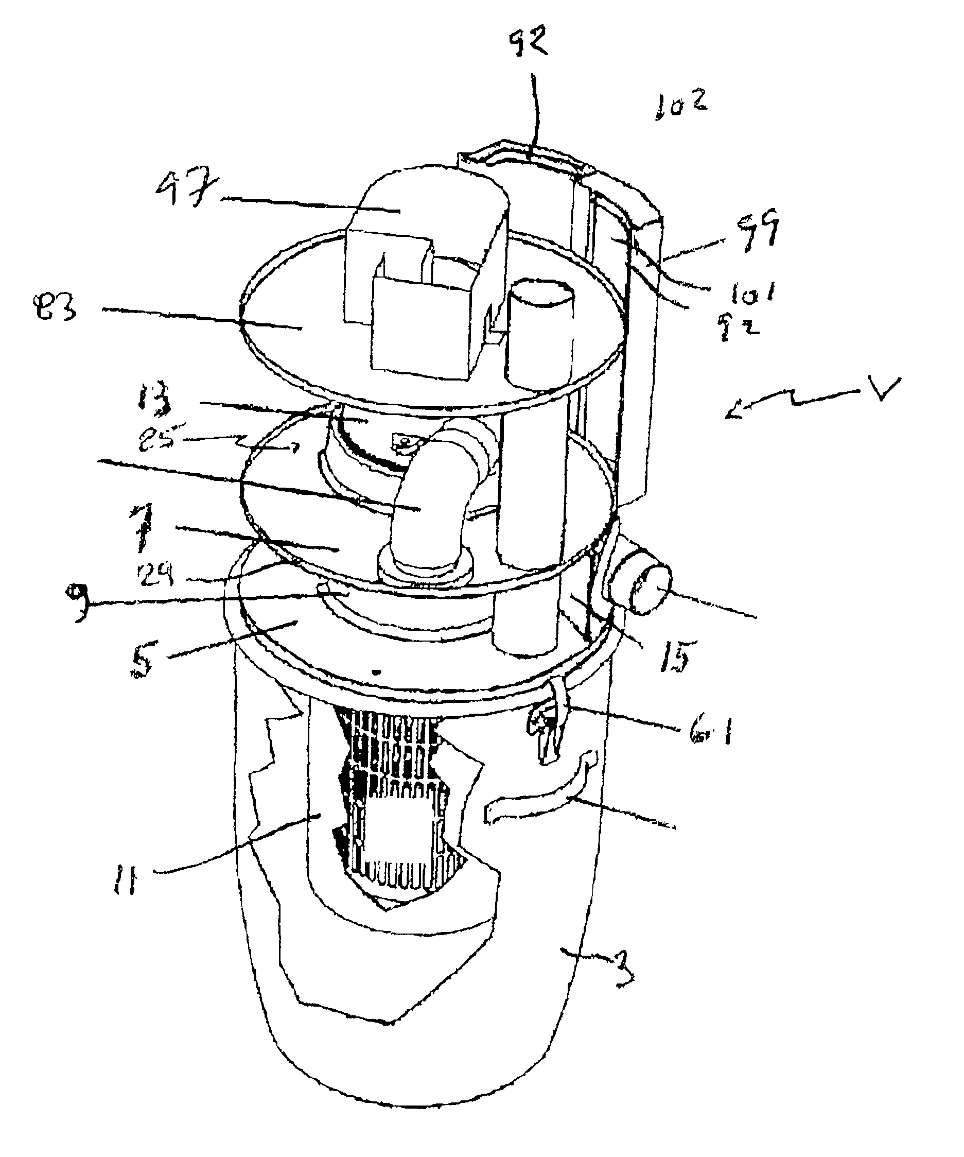
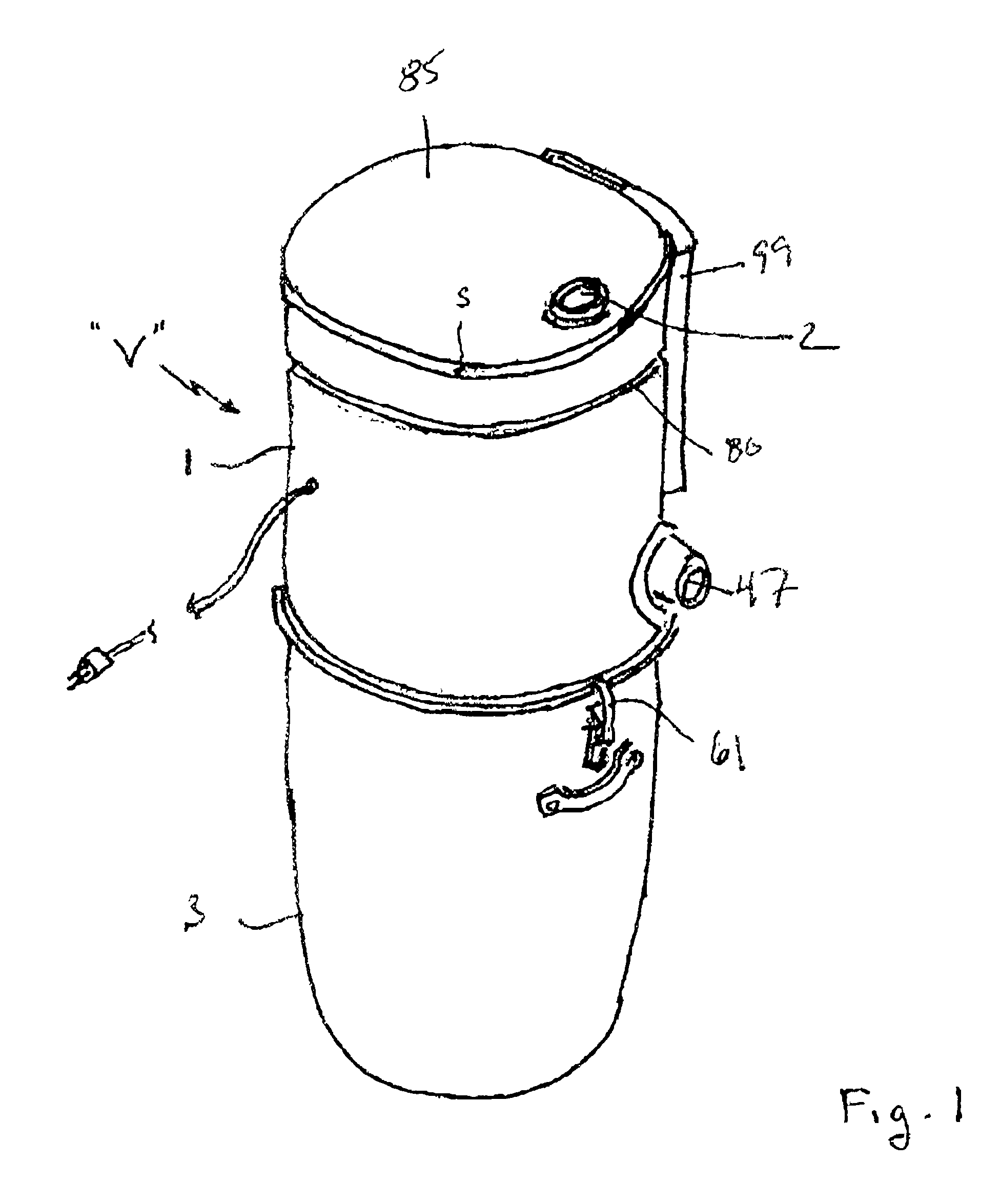
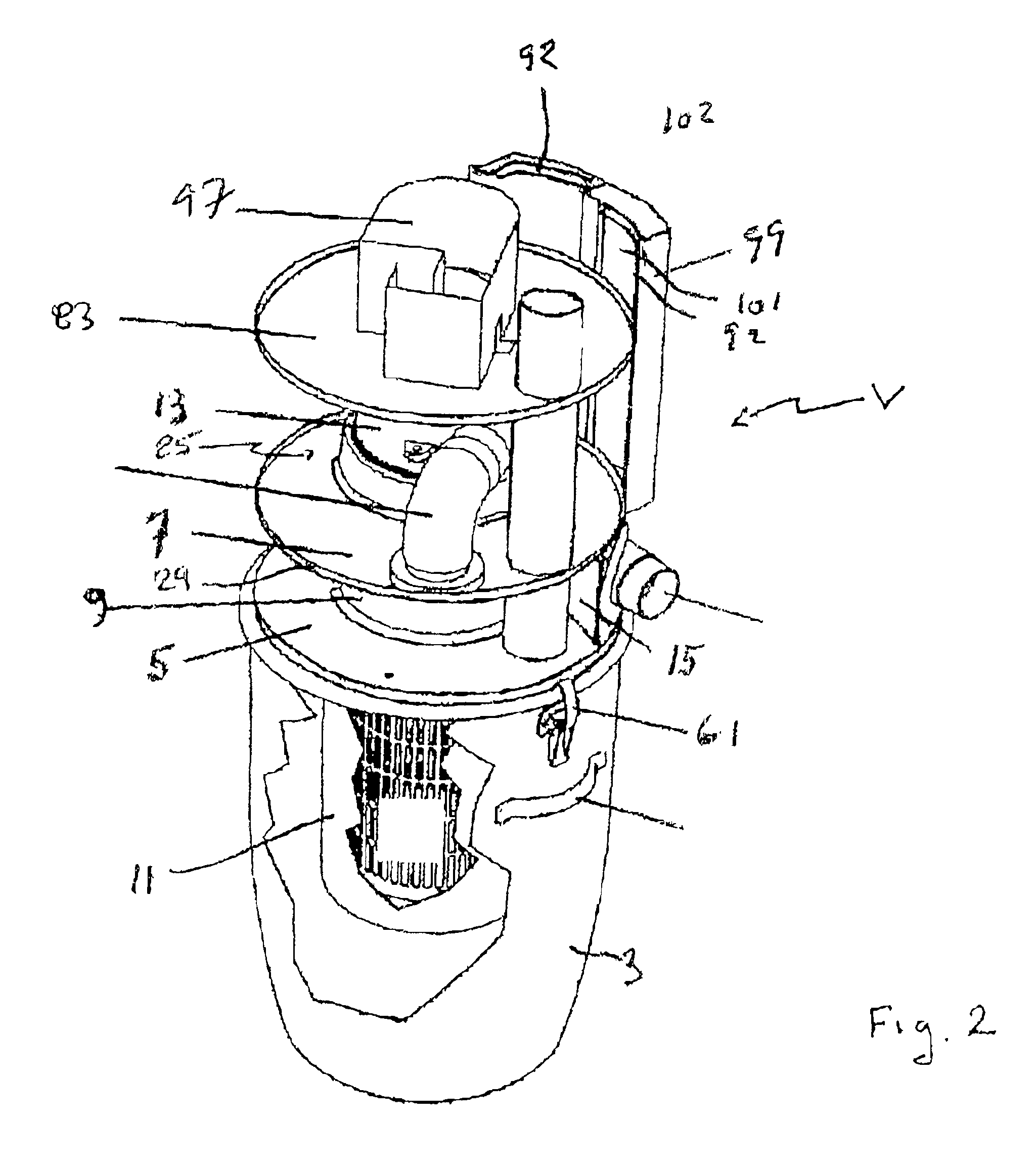
As illustrated in the drawings, the present invention preferably refers to a central vacuum power unit "V" comprising in combination a canister 1, a debris collection chamber 3, a first plate 5, a second plate 7, a duct means 9, a filtering means 11, a motor-fan assembly 13, a first baffle means 15, means 17 for generating a flow of cooling air for the electric motor 21. Advantageously, the debris collection chamber 3 is in fluid communication with an air intake 2 for the working air loaded with debris Optionally, this air intake may be in fluid communication with a tubing 4 positioned between said air intake and said debris collection chamber.

The canister 1 has a sidewall 23 and a hollow interior 25. The sidewall 23 may be advantageously made of any appropriate material such as for example from a sheet of steel or a sheet of aluminum. Preferably, as illustrated, the canister may have a cylindrical hollow interior 25.

The first plate 5 advantageously extends across said hollow interi...


PUM


Abstract

The present invention relates to a central vacuum power unit comprising in combination a canister, a chamber for collecting debris, a first plate, a second plate, a third plate, a duct, a motor-fan assembly, a filter, and a first baffle. The duct extends between the first and second plates and is in fluid flow communication with respective openings defined in the first and second plates. The sidewall of the canister, the first and the second plates and the duct defines an acoustic damping chamber covered with a lining of sound absorbing material.

Description

The invention relates to a central vacuum power unit and more particularly to a central vacuum power unit allowing to substantially reduce the level of noise emitted.DESCRIPTION OF THE PRIOR ARTA central vacuum cleaner comprises a power unit usually installed permanently in an area of a building and one or more ducts are connected to vacuum system intlets provided in various zone all over said building. Said cleaner allows to clean any areas of said building with the use of a flexible hose or other debris recuperation device connected to said intlets. Said central vacuum power unit can be activated by mere insertion of the hose in one of saids inlets which is electrically wire to said unit, or by a switch provided on the hose or in the debris recuperation device, or by any other means.Because habitable surfaces in recent buildings are optimized, a central vacuum power unit is frequently installed near a living space. However, said power unit generates high levels of noise. Therefore...

Claims


Application Information

Patent Timeline
Patent Type & Authority Patents(United States)
IPC IPC(8): A47L5/38A47L5/22A47L9/00
CPCA47L5/38A47L9/0081
Inventor PLOMTEUX, ALEXANDREBIZIER, REYNALDCLOUTIER, JACQUES
Owner NUERA SOLUTIONS AIR NUERA AIR SOLUTIONS
Why Eureka
Try Eureka