Variable valve timing apparatus

a timing apparatus and variable valve technology, applied in mechanical equipment, valve arrangements, machines/engines, etc., can solve the problems of difficult engine starting, difficulty in ensuring the hydraulic pressure required to lock the rotor, and insufficient supply of hydraulic oil

Inactive Publication Date: 2004-08-24
DENSO CORP
View PDF8 Cites 57 Cited by
  • Summary
  • Abstract
  • Description
  • Claims
  • Application Information

AI Technical Summary

Benefits of technology

According to one aspect of the present invention, the variable valve timing apparatus has the first member for restricting a rotor's rotating to a part of operating range and the second member for locking the rotor at an intermediate position. As a result, the first member can prevent the rotor from reaching an undesirable range. On the other hand, the releasing of restriction of the rotation of the rotor by the first member can allow the rotor to rotate to the restricted range. For this reason, it is possible to realize a suitable valve timing as required. Further, since the second member fixes the rotor at the intermediate position, it can prevent the undesirable rotation of the rotor.
According to another aspect of the present invention, the variable valve timing apparatus has a rotor rotation restricting unit having a restricting pin for restricting the rotation of the rotor. This restricting pin moves according to a pressure difference between the first control chamber and the second control chamber. The restricting pin can restrict the rotation of the rotor and can prevent the rotor from reaching an undesirable range. On the other hand, the releasing of restriction of the rotation of the rotor can rotate the rotor within a wide range. As a result, it is possible to realize a suitable valve timing as required. Further, it is possible to control the restricting pin according to the pressure balance between the first control chamber and the second control chamber. For example, it is possible to lock the restricting pin at a restricting position.
According to still another aspect of the present invention, the variable valve timing apparatus has a lock pin for locking the rotor and a delay angle restricting pin for preventing the rotor from rotating from the intermediate position to a delay angle side. This delay angle restricting pin is urged by a spring to a restricting position and is moved by hydraulic pressure to a restriction releasing position. Therefore, the delay angle restricting pin is moved to the restricting position when the hydraulic pressure is decreased. Even when an engine speed is low and the hydraulic pressure is low, or even when an oil temperature is high and thus the hydraulic pressure becomes low, it is possible to surely keep the delay angle restricting pin at the restricting position.
According to still another aspect of the present invention, the variable valve timing apparatus has a restricting pin for restricting the rotational range of the rotor. The restricting pin is moved to the restricting position by a spring. The restricting pin is supplied with the hydraulic pressure by an exclusive oil passage provided independently of an oil passage for supplying the hydraulic pressure for rotating the rotor, thereby being moved to the restriction releasing position. The exclusive oil passage makes it possible to control the restricting pin without affecting the hydraulic pressure for rotating the rotor. For example, even when the engine speed is low and the hydraulic pressure is low, or even when the oil temperature is high and thus the hydraulic pressure becomes low, it is possible to surely keep the delay angle restricting pin at the restricting position.
According to still another aspect of the present invention, the variable valve timing apparatus has a pin which can move to three positions. The pin allows the rotor to freely rotate at the first position and restricts the rotational range of the rotor at the second position and locks the rotation of the rotor at the third position. Therefore, it is possible to selectively realize the restricting of rotation of the rotor and the locking of the rotor by only one pin.

Problems solved by technology

However, when the number of revolution is low, in particular, when the temperature of the hydraulic oil is high, there is the case where the hydraulic pressure is decreased to make it impossible to secure the hydraulic pressure required to lock the rotor at the intermediate phase position.
Further, there is a problem that when an engine stall occurs, the rotor moves to and stops at the largest delay angle position to make it difficult to start the engine again.
However, since the hydraulic pump 27 stops, the hydraulic oil is not supplied to the delay angle chamber 7.

Method used


Image

  • Variable valve timing apparatus
  • Variable valve timing apparatus
  • Variable valve timing apparatus

Examples


eleventh embodiment

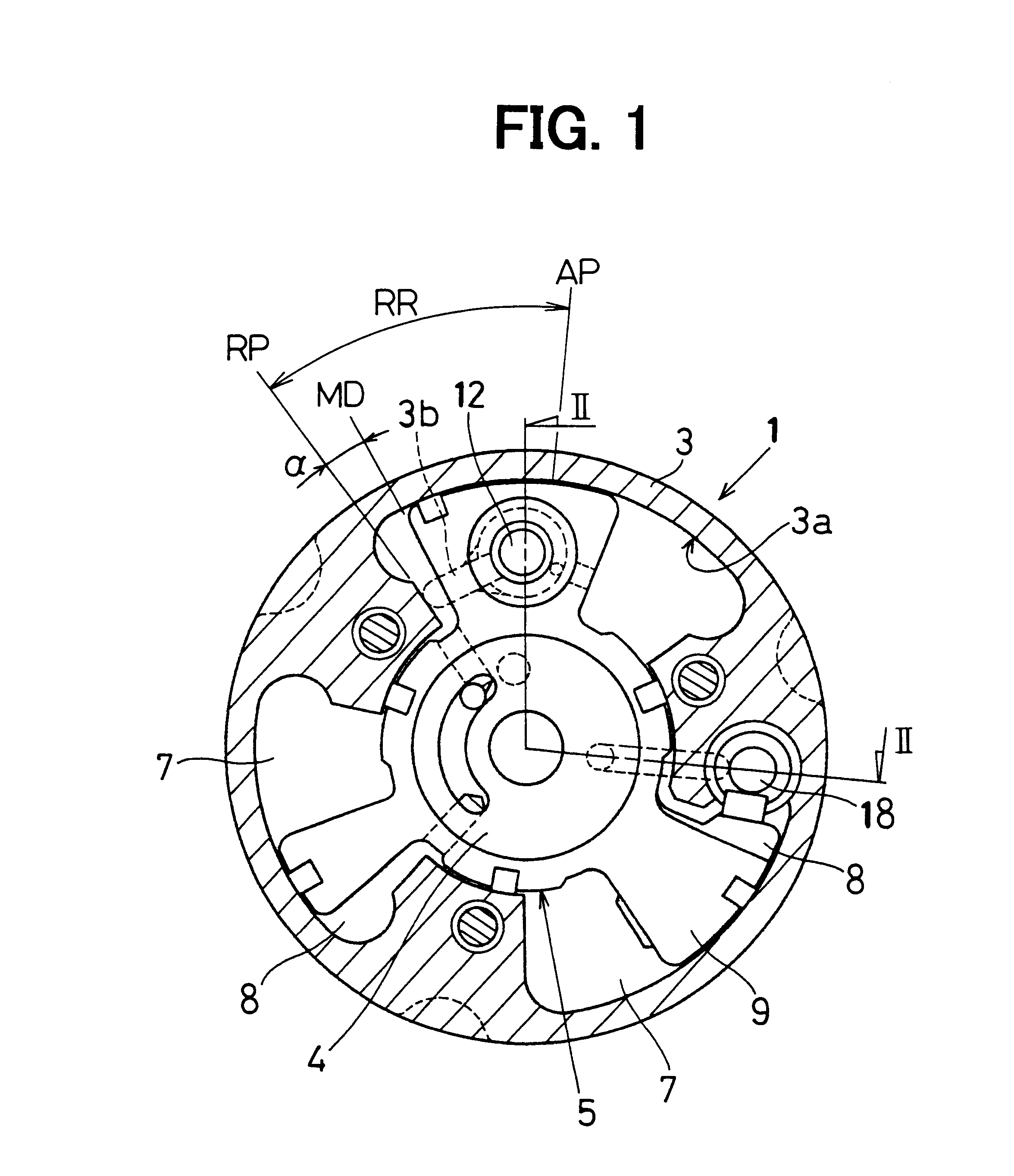
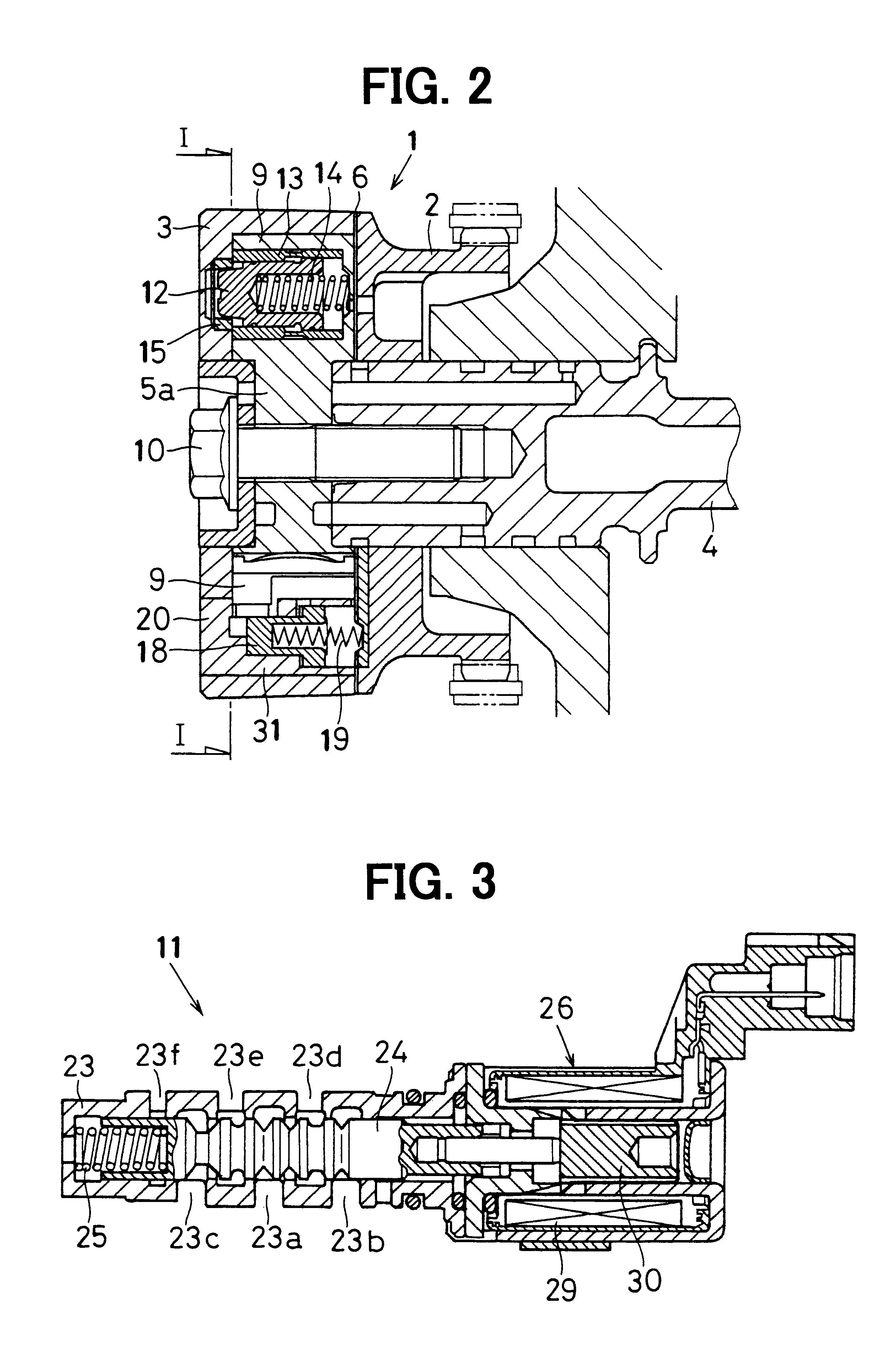
FIG. 36 is a cross sectional view of a VVT 1 and FIG. 37 is a front view in the axial direction of the VVT 1. In the VVT 1 of the present embodiment, an exclusive oil passage 108 is formed in a bolt 110 for fixing a rotor 5 and a hydraulic control valve 105 for opening or closing the communication between the exclusive oil passage 108 and a drain space is fixed to the front side (left side of the case 3) of the VVT 1.

The exclusive oil passage 108, as shown in FIG. 36, communicates with an oil reservoir 117 made in a camshaft 4. An orifice 118 is disposed between the exclusive oil passage 108 and the oil reservoir 117. The exclusive oil passage 108 communicates with a lock depression 24 via a housing 3 side.

The hydraulic control valve 105 opens when an advance angle restricting pin 112 (which serves as a lock pin) is fitted in the lock depression 115 to lock the rotor 5 at the normal delay angle position and closes when the prevention of rotation of the rotor 5 by the advance angle r...

twelfth embodiment

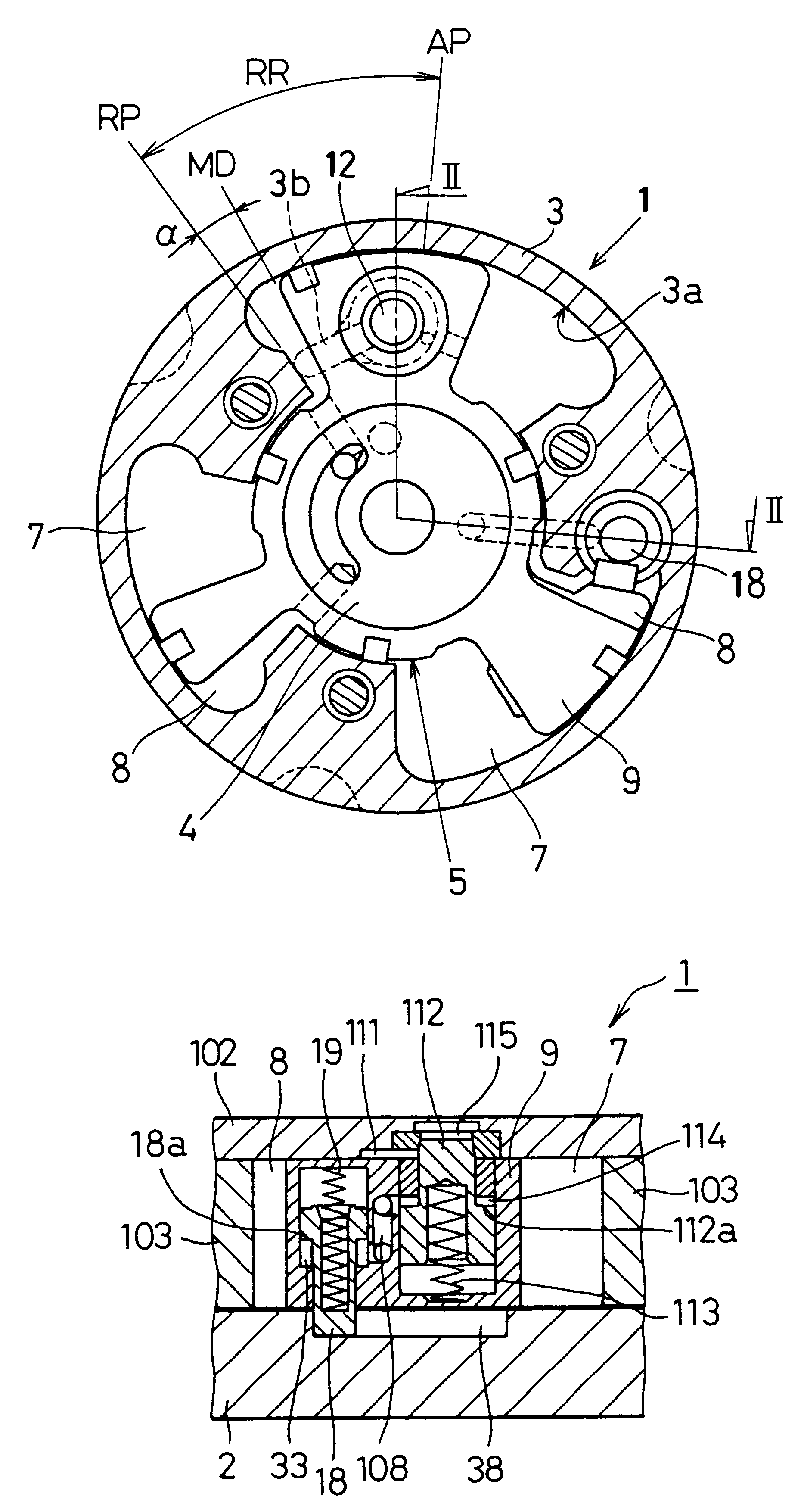
FIG. 42 is a cross sectional view of the vicinity of an advance angle restricting pin 112 and a delay angle restricting pin 18. The present embodiment is an example in which an oil discharging port 120 and a pressure releasing port 121 are formed to eliminate the effect of the hydraulic pressure on the motion of the advance angle restricting pin 112. The pins 18, 112 are disposed to have operating direction opposite to the operating direction of the pins 18, 112 of the tenth embodiment. Here, since the basic constitution of the VVT is the same as in the tenth embodiment, the oil discharging port 120 and the pressure releasing port 121 will be described.

The oil discharging port 120 is an passage for discharging the hydraulic oil leaking to an advance angle restricting groove 111 from a hydraulic chamber (a delay angle chamber 7 and an advance angle chamber 8) and is formed in a sprocket 2, as shown in FIG. 42, to open a lock depression 115 made at the end portion of the advance angle...

thirteenth embodiment

FIG. 47 is a cross sectional view of the vicinity of an advance angle restricting pin 112 and a delay angle restricting pin 18, and FIG. 48 is a plan view of the advance angle restricting pin 112 with a sprocket 2 removed when viewed from the tip end side thereof. The present embodiment is an example in which a communication groove 124 for making an advance angle restricting groove 111 communicate with a control chamber 114 is formed in place of the oil discharging port 120 shown in the twelfth embodiment.

As shown in FIG. 47, in a vane 9 is incorporated a cylindrical bearing 125 for slidably locking the advance angle restricting pin 18. The inner circumferential surface of the bearing 125 is depressed to form the communication groove 124. The communication groove 124, as shown in FIG. 48, is formed between the bearing 125 and the advance angle restricting pin 18 in the direction nearly perpendicular to the rotational direction of the rotor 5. Since the hydraulic oil leaking to the a...


PUM


Abstract

A variable valve timing apparatus rotatably receives a rotor in a housing. The rotor can rotate within a predetermined angular range. In some cases, the rotor is locked by a lock pin at an intermediate position within the angular range. In this manner, it is possible to realize a suitable valve timing even when an engine is restarted after it is stopped. In some case, the rotor is prevented from moving to the largest delay angle position by a restricting pin. In this manner, it is possible to prevent the rotor from reaching the largest delay angle position before the engine is stopped. On the other hand, while the engine is operated, it is possible to rotate the rotor to the largest delay angle position and to realize a valve timing responsive to the state of operation.

Description

This application is based on Japanese Patent Applications No. 2001-92350 filed on Mar. 28, 2001, No. 2001-98078 filed on Mar. 30, 2001, No. 2001-285280 filed on Sep. 19, 2001, and No. 2002-13119 filed on Jan. 22, 2002 the contents of which are incorporated herein by reference.1. Field of the InventionThe present invention relates to a variable valve timing apparatus for varying an opening / closing timing of an intake valve or an exhaust valve of an internal combustion engine.2. Description of Related ArtA variable timing mechanism is disclosed in JP-A No. 9-324613. This variable timing mechanism employs a lock pin capable of locking a rotor at a position (hereinafter referred to as intermediate phase position) where the rotor rotates a predetermined angle to an advance angle side from the largest delay angle position. When an engine starts, this lock pin is engaged with a lock depressed portion to lock the rotor at the intermediate phase position to thereby provide a given valve timi...

Claims


Application Information

Patent Timeline
Patent Type & Authority Patents(United States)
IPC IPC(8): F01L1/344F01L1/34
CPCF01L1/34F01L1/344F01L2001/3443F01L2001/34466F01L2001/34469F01L2001/34473F01L2001/34476F01L2001/34483F01L1/3442
Inventor TAKENAKA, AKIHIKOKUSANO, SHIGEYUKIYAMADA, HIROHIKO
Owner DENSO CORP
Why Eureka
Try Eureka