
Circumcision clamp

a technology of circumcision and clamping rod, which is applied in the field of circumcision clamp, can solve the problems of high cost, heavy weight, and high cost of medical doctors, and achieve the effect of low manufacturing cos

Inactive Publication Date: 2004-08-24
MORGAN STANLEY
View PDF18 Cites 15 Cited by
  • Summary
  • Abstract
  • Description
  • Claims
  • Application Information

AI Technical Summary

Benefits of technology

In view of the foregoing background, it is therefore an object of the present invention to provide a lightweight and dependable circumcision clamp having low manufacturing costs. Another object of the present invention is to provide a circumcision clamp that can be refurbished and resterilized for reuse. These and other objects, features, and advantages of the present invention, are provided by a circumcision clamp for performing a circumcision operation and including an engaging section for receiving prepuce to be removed during a circumcision procedure, securing means for tightly maintaining the engaging section in a closed position and for releasing the engaging section to be opened. The securing means includes a latching member and a handle movably connected thereto. The clamp also has a pair of pivot connections for respectively connecting a first end of the latching member to the engaging section and a second end of the latching member to the handle. Each of the pivot connections includes a pivot pin. A passage is adjacent to one of the pivot connections into which a corresponding one of the pivot pins is at least partially displaceable when force is exerted against the one pivot pin in a direction generally toward the passage for causing the one pivot pin to be displaced from its original position into a position in which the circumcision clamp becomes inoperative.
The passage has a width narrower than the diameter of the one pivot pin so that same can only partially enter the passage when sufficient pressure is applied to the one pivot pin in a general direction of the passage. The passage is juxtaposed to the one pivot connection and both are located at the second end of the first member. The passage extends from the one pivot connection towards an outer edge of the first member. The second end of the first member is bifurcated and has an upper portion and a lower portion for receiving the first end of the latching member therebetween. The passage is located in at least one of the bifurcated upper and lower portions of the first member. The latching member and pins are formed of steel and remaining elements of the clamp are formed of plastic material. Advantageously, the present invention will be lighter, yet just as strong as prior art circumcision instruments made from stainless steel, for example, as well as more affordable for the patient.

Problems solved by technology

As a result, hospitals and medical doctors are burdened with the higher costs associated with the manufacture and employment of a new circumcision instrument for each patient.
Unfortunately, the costs of this shortcoming are ultimately passed on to the patients.
Unfortunately, some shortcomings of such a circumcision clamp are its relatively high cost and heavy weight as well as wear on the cam lever which effects the proper functioning of the clamp during use.
In addition, such clamps include a hook latch member that breaks off after each use thereby making the clamp inoperable and disposable.
Unfortunately, a shortcoming of such prior art circumcision clamps is their inability to be refurbished for reuse.
Unfortunately, similar to other prior art clamps, a shortcoming of these clamps is their inability to be refurbished for reuse.

Method used


Image

  • Circumcision clamp
  • Circumcision clamp
  • Circumcision clamp

Examples


Embodiment Construction

The present invention will now be described more fully hereinafter with reference to the accompanying drawings, in which preferred embodiments of the invention are shown. This invention may, however, be embodied in many different forms and should not be construed as limited to the embodiments set forth herein. Rather, these embodiments are provided so that this application will be thorough and complete, and will fully convey the true scope of the invention to those skilled in the art. Like numbers refer to like elements throughout, and prime and double prime notations are used to indicate similar elements in the two embodiments set forth herein.

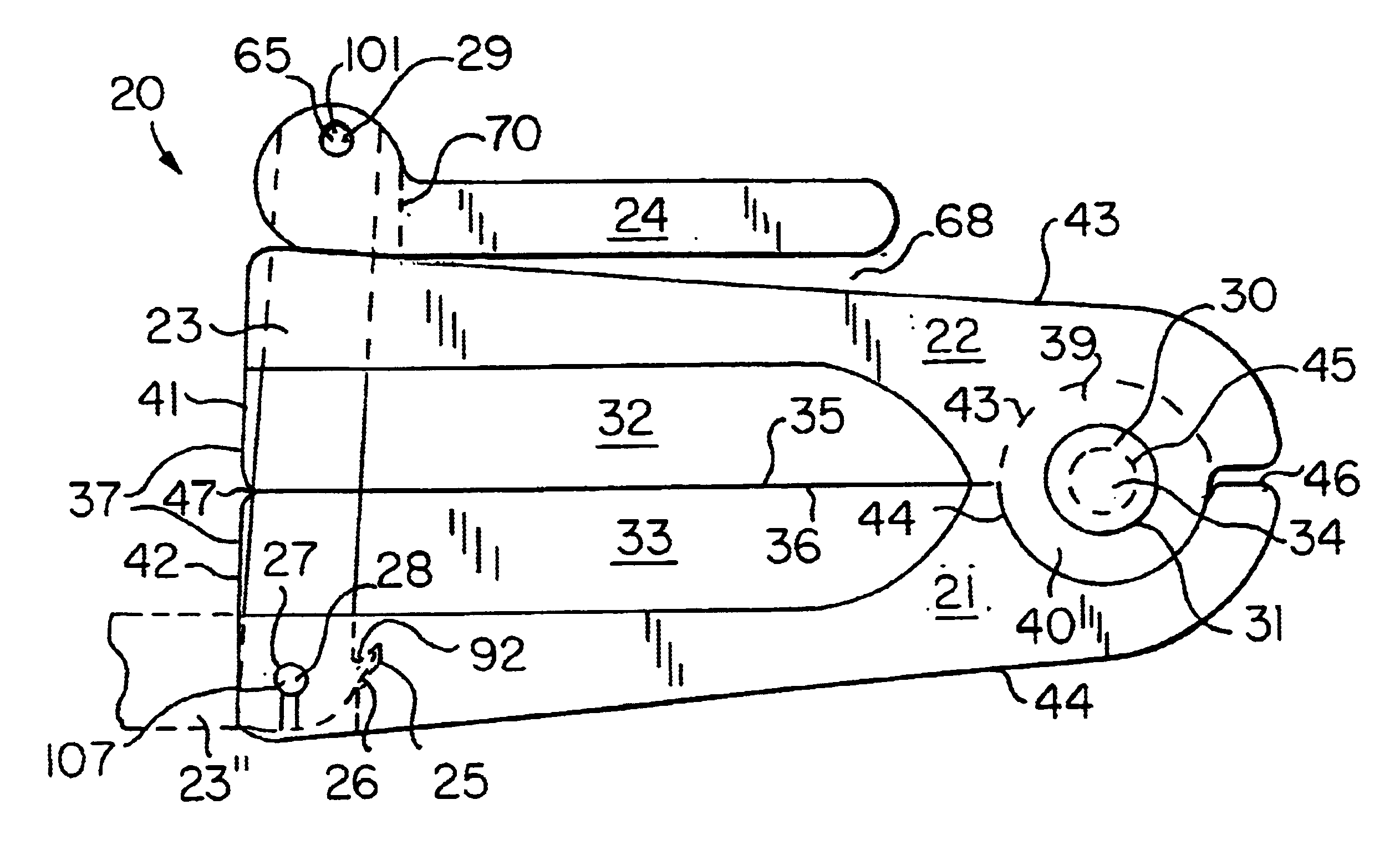
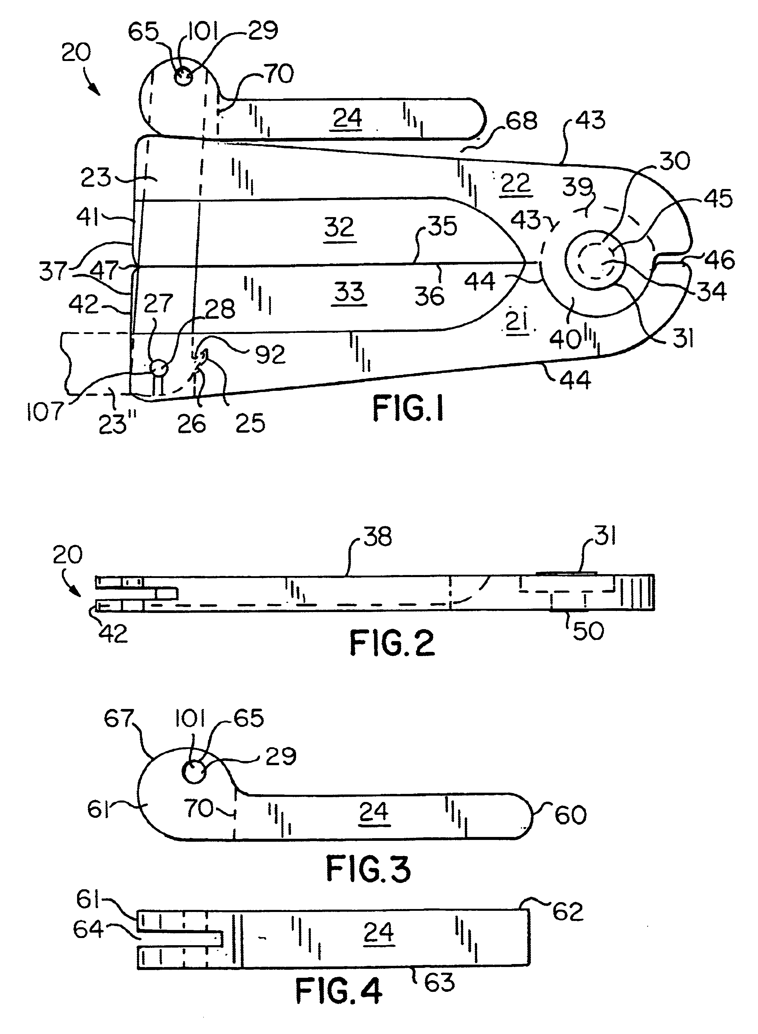
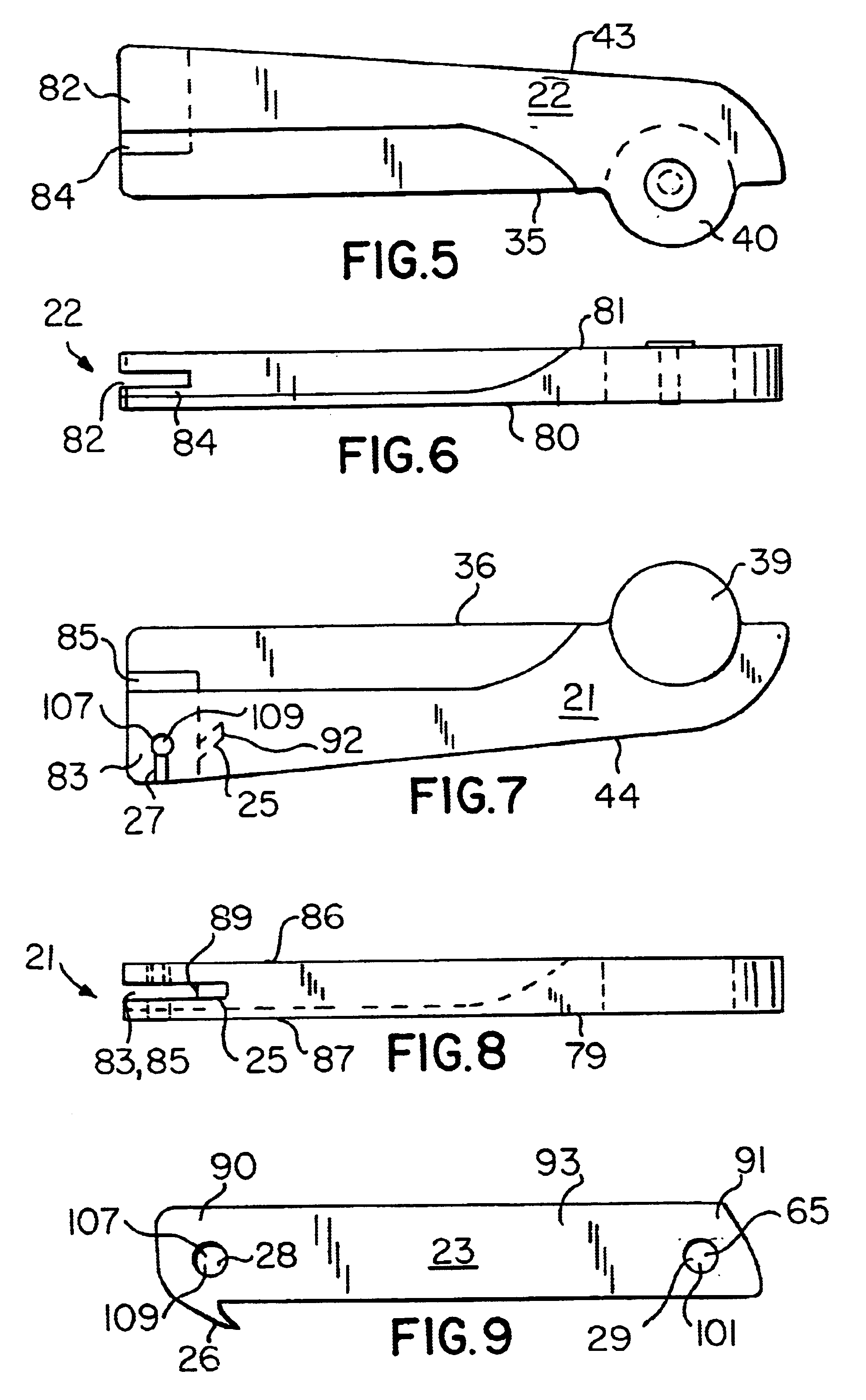
Referring initially to FIGS. 1 and 2, a circumcision clamp 20 for performing a circumcision operation is shown. Clamp 20 includes an upper or first elongate member 21 and a lower or second elongate member 22, latching member 23, handle 24, and a plurality of pivot connections 107, 101, 34 secured by a plurality of pivot pins 28-30, respective...


PUM


Abstract

The clamp includes a passage adjacent to a pivot connection and into which a corresponding pivot pin is at least partially displaced from its original position into a position in which the circumcision clamp becomes inoperative. In one embodiment, the passage is located at one end of the latching member having a notch that is adjacent to a spur so that, when the clamp is moved to a closed position, the spur slips into the notch. The spur and notch resist movement of the latching member thereby causing the pivot pin to be forcibly displaced from its original position into an inoperative position. Select elements of the clamp may be formed of transparent plastic material for allowing a circumcision operator to monitor the glans penis therebeneath so that same is not damaged during a circumcision. Alternately, the clamp may be formed of aluminum and stainless steel. In such an embodiment, the passage is located at one end of the handle. As the handle moves to an open position from a closed position, the corresponding pivot pin at the end of the handle is forcibly displaced at least partially into the passage and thereby rendering the clamp inoperative. Such an embodiment of the clamp may be sent back to the manufacturer to be refurbished and resterilized for reuse.

Description

CROSS REFERENCE TO RELATED APPLICATIONSNot Applicable.STATEMENT REGARDING FEDERALLY SPONSORED RESEARCH OR DEVELOPMENTNot Applicable.REFERENCE TO A MICROFICHE APPENDIXNot Applicable.BACKGROUND OF THE INVENTION1. Technical FieldThis invention relates to a circumcision clamp and, more particularly, to a circumcision clamp having a pivot pin that becomes offset after performing a circumcision procedure and thereby rendering the clamp inoperative to perform another circumcision.2. Prior ArtCircumcision instruments are well known in the art. Such instruments are commonly used to remove prepuce from a penis for medical and / or religious reasons, for example. Some conventional circumcision instruments may be discarded after performing a circumcision procedure for ensuring that sterile and dependable circumcision instruments will be employed in subsequent procedures. As a result, hospitals and medical doctors are burdened with the higher costs associated with the manufacture and employment of...

Claims


Application Information

Patent Timeline
Patent Type & Authority Patents(United States)
IPC IPC(8): A61B17/326
CPCA61B17/326
Inventor FREEDMAN, DONALD S.CAMPBELL, DAVID F.
Owner MORGAN STANLEY
Learn More