Delivery system for liquid catalysts

a technology of liquid catalysts and delivery systems, which is applied in the direction of liquid-gas reaction processes, continuous combustion chambers, machines/engines, etc., can solve the problems of liquid being forced through the air inlet and overflow from the system, system ineffective and inefficient, and catalyst solution consumption at an uncontrolled ra

Inactive Publication Date: 2004-09-07
EPS TECH +2
View PDF32 Cites 19 Cited by
  • Summary
  • Abstract
  • Description
  • Claims
  • Application Information

AI Technical Summary

Benefits of technology

The foregoing and other features and advantages of the present invention will be apparent from the following more detailed description of the particular embodiments of the invention, as illustrated in the accompanying drawings.

Problems solved by technology

With this arrangement, the catalyst solution from the bursting bubbles may directly splash into the sparging gas outlet and travel to the flame zone in liquid form rather than as a sparging gas, quickly consuming the catalyst solution at an uncontrolled rate.
This unnecessary and uncontrolled consumption causes the system to become ineffective and inefficient.
Another undesirable aspect of conventional delivery systems is that if, instead of the negative pressure of a vacuum, positive pressure occurs in the receptacle above the liquid, the liquid may be forced through the air inlet and overflow from the system.
One specific limitation of conventional sparging gas catalyst delivery systems is that the catalyst delivery rate of the system is either fixed or proportional to the vacuum rate of the combustion system and cannot be automatically enriched with increased demand.

Method used


Image

  • Delivery system for liquid catalysts
  • Delivery system for liquid catalysts
  • Delivery system for liquid catalysts

Examples


Embodiment Construction

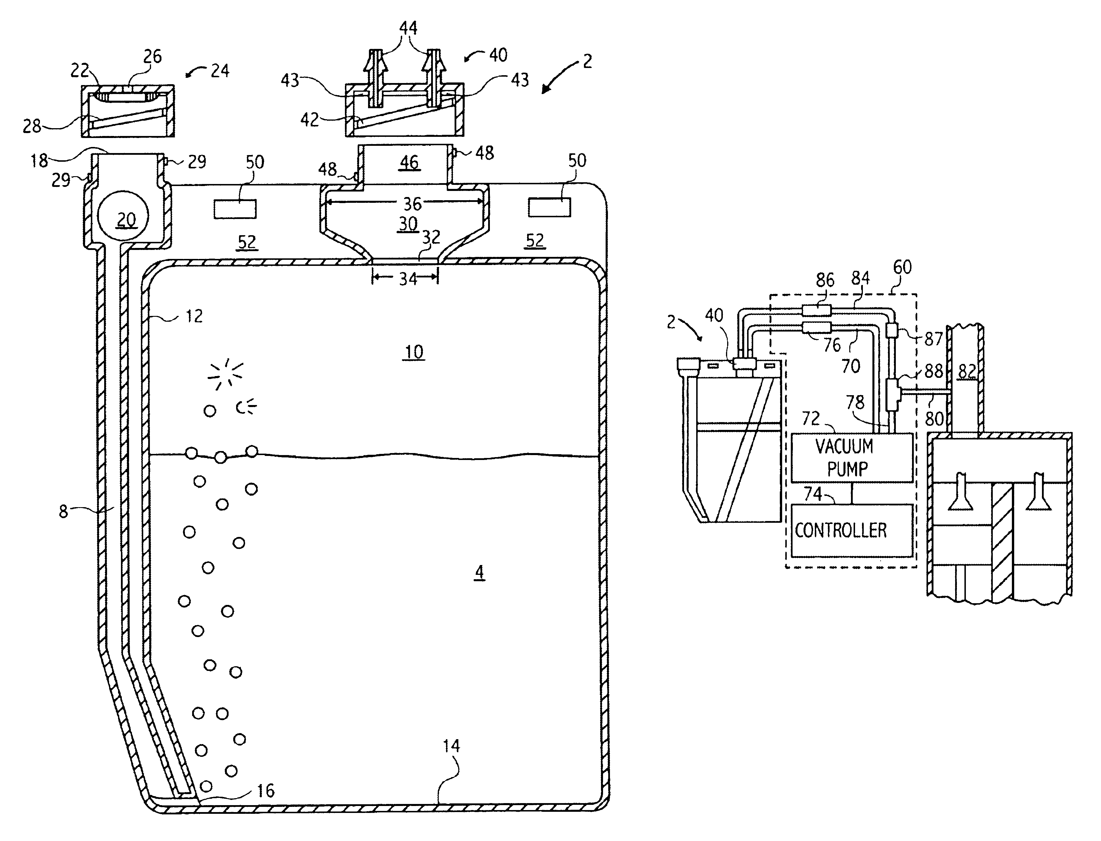
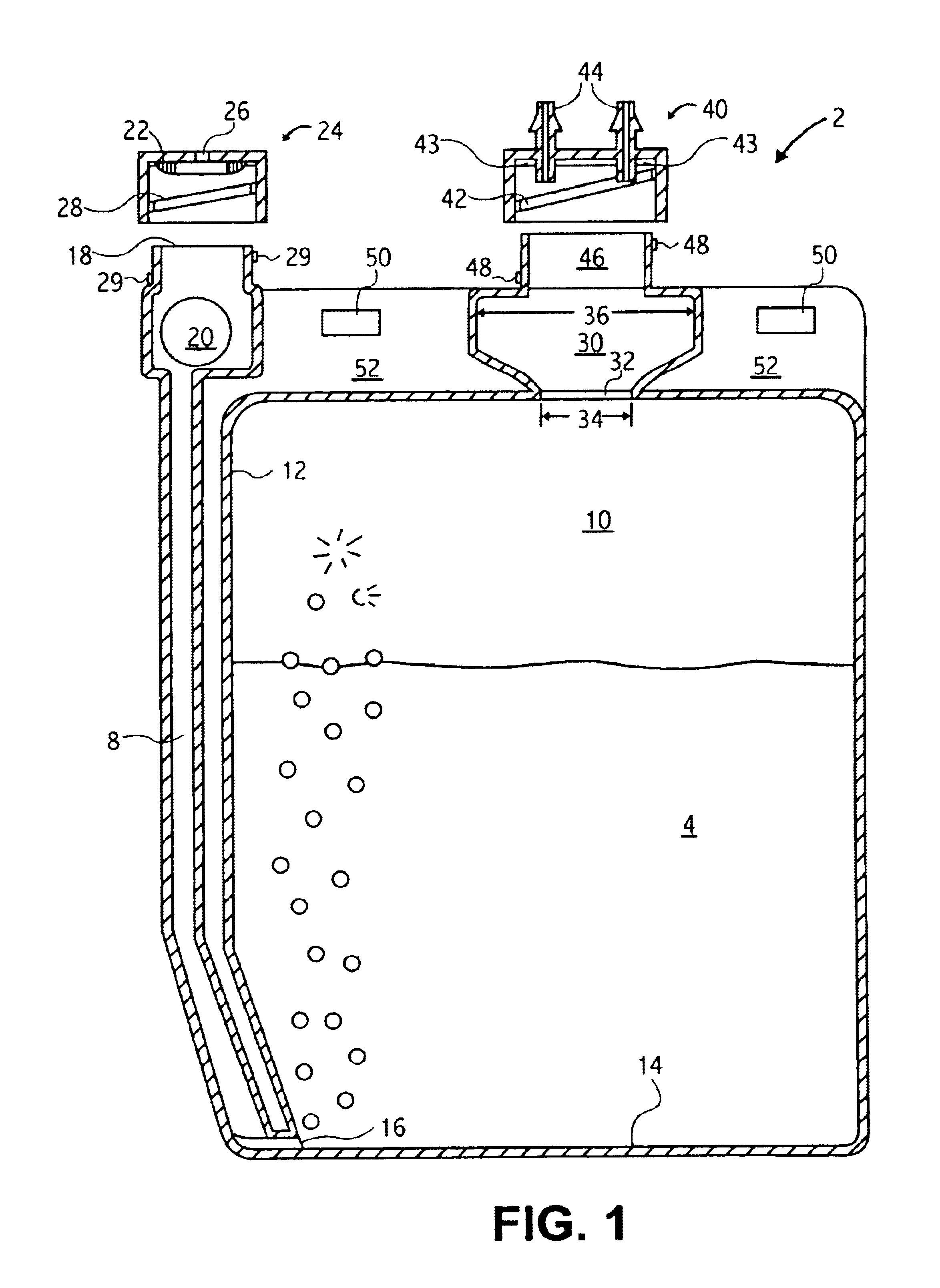
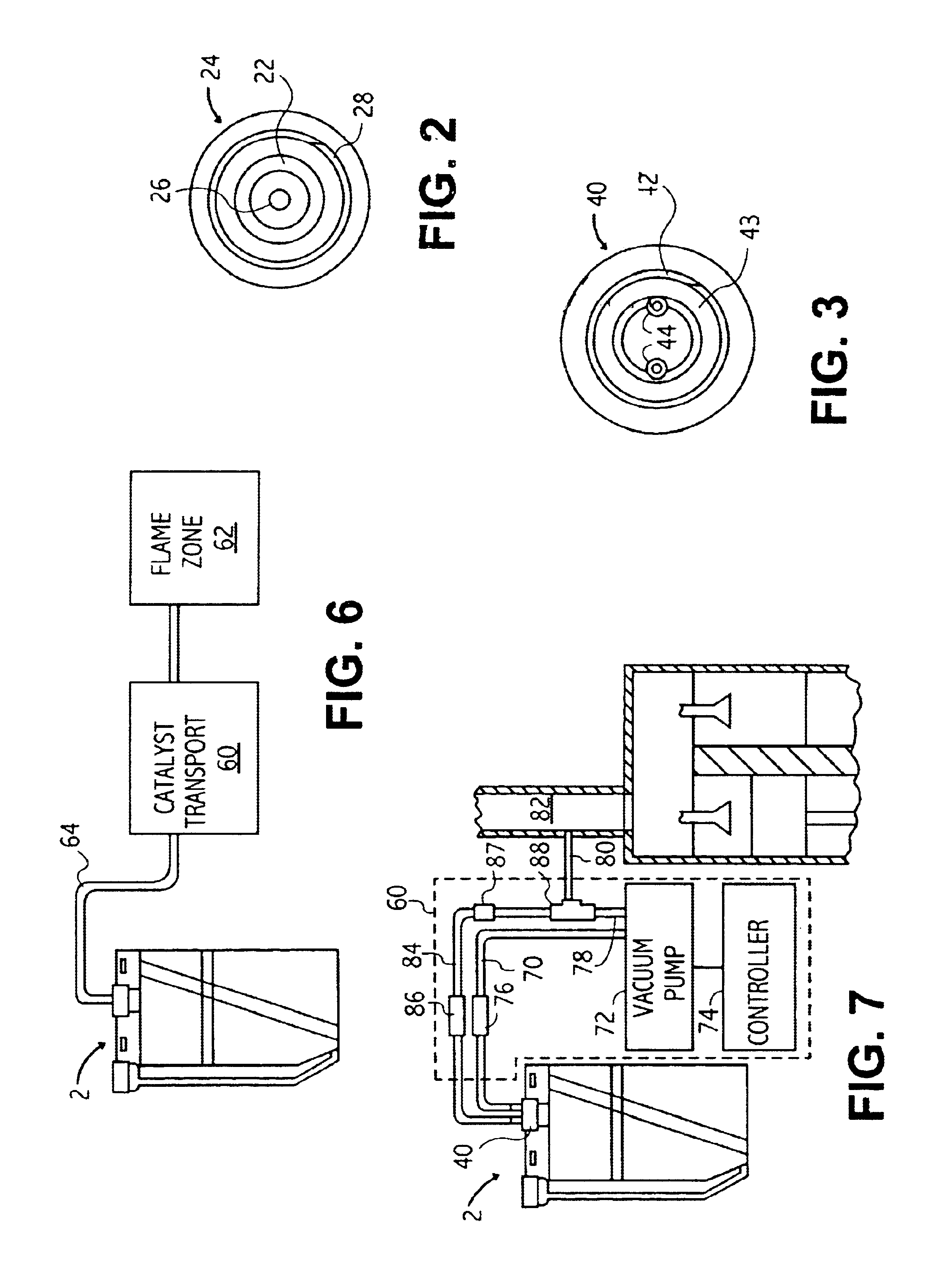
As discussed above, embodiments of the present invention relate to a liquid catalyst delivery system for a combustion reaction whereby catalyst is transported in sparging gas form to the flame zone of the combustion reaction. As used herein, "flame zone" refers to the region where the combustion reaction occurs. In cases where the combustion reaction is enclosed within a combustion chamber, such as within the piston chamber of a reciprocating piston engine, the flame zone is the space within the combustion chamber. In other cases where the combustion reaction is not within a combustion chamber but is, instead, open to the environment, such as with many open flame applications, the flame zone is the region in which combustion of any fuel may occur.

FIG. 1 illustrates an embodiment of a liquid catalyst receptacle 2 for use in a catalyst delivery system of the present invention. In the catalyst delivery system shown in FIG. 1, the receptacle 2 contains a catalyst mixture 4. Examples of ...


PUM

PropertyMeasurementUnit
depthsaaaaaaaaaa
diametersaaaaaaaaaa
diameteraaaaaaaaaa

Abstract

A delivery system for generating a sparging gas containing catalyst particles and delivering them to a flame zone of a combustion reaction is disclosed. A catalyst mixture receptacle for the delivery system includes a floating ball check valve on an air inlet to an inlet tube of the receptacle which is spaced from a vertical wall of the receptacle. A secondary splash chamber having an opening smaller than the body of the chamber is also included between the main body of the receptacle and the sparging gas outlet for the receptacle to reduce the opportunity for catalyst mixture in liquid form to reach the sparging gas outlet. An enrichment circuit is disclosed including a controller, pump, and a one-way check valve for adding additional sparging gas to a flame zone of a combustion process in times of added load. The receptacle may be mounted with a vibrator, such as the pump, to increase the consistency of the bubbles in the sparging process. Alarms and indicators, including remote alarms and indicators, may also be included to relay pertinent information regarding the delivery system. The sparging gas may thereafter be pressurized and injected in particular applications.

Description

1. Technical FieldThis invention generally relates to a system for delivering a catalyst into a flame zone of a combustion reaction, such as a fuel combustion chamber. More specifically, embodiments of the invention include a catalyst reservoir which produces an catalyst-containing aerosol, vapor or sparging gas and a catalyst transport system to transport the catalyst to the flame zone. Specific embodiments of the invention may include a vacuum source to draw the catalyst-containing gas to the flame zone and an enrichment circuit to cause an increase in the amount of catalyst being drawn to the flame zone when increased catalyst enrichment is required.2. Background ArtSparging gas, catalyst vapors and aerosols have been used in the combustion reaction art to increase the energy output of fuel combustion systems. In conventional sparging gas delivery systems, a vacuum is created above a pool of liquid in a receptacle to cause atmospheric air to be drawn into the receptacle at a loca...

Claims


Application Information

Patent Timeline
Patent Type & Authority Patents(United States)
IPC IPC(8): B01J4/00B01F3/04B01J10/00F23D14/46F23D14/68F23J7/00F27D23/00F27D7/00F27D7/02F02M25/00B01F33/40F23R3/40F27D99/00
CPCB01F3/04007B01J4/008B01J10/002F23D14/68F23J7/00F27D99/0033B01F2215/0085B01J2219/00164B01J2219/00225B01J2219/00268F23L2900/00001F27D7/02B01F23/21B01F2101/501
Inventor HASKEW, JAMES W.
Owner EPS TECH
Why Eureka
Try Eureka