Method for rapid thermal cycling of biological samples

a biological sample and temperature control technology, applied in the field of apparatus for rapid control of the temperature of liquid samples, can solve the problems of affecting the transfer of thermal energy, the disadvantages of microfuge tubes, and the use of heat block type devices as heat control systems, so as to reduce the overall thermal mass, shorten the temperature versus time profile, and increase the yield and specificity of polymerase chain reactions.

Inactive Publication Date: 2004-09-07
THE UNIV OF UTAH
View PDF39 Cites 128 Cited by
  • Summary
  • Abstract
  • Description
  • Claims
  • Application Information

AI Technical Summary

Benefits of technology

In view of the above described state of the art, the present invention seeks to realize the following objects and advantages.
The device 10 of the present invention, due to its lower overall thermal mass, is capable of cycling samples through significantly shortened temperature versus time profiles compared to the prior art. The DNA amplification application of the embodiment of FIGS. 1-3 can pass through a temperature versus time profile cycle in 30-60 seconds (see FIG. 5). This same cycle using prior art devices would take approximately 5-10 times longer. These low cycle times have proven also to increase yield and specificity of the polymerase chain reaction over prior art cycling.

Problems solved by technology

However, the inability to quickly and accurately adjust the temperature of the heat blocks through a large temperature range over a short time period, has rendered the use of heat block type devices undesirable as a heat control system when carrying out the polymerase chain reaction.
Moreover, the microfuge tubes which are generally used have disadvantages.
The material of the microfuge tubes, their wall thickness, and the geometry of microfuge tubes is a hinderance to rapid heating and cooling of the sample contained therein.
The plastic material and the thickness of the wall of microfuge tubes act as an insulator between the sample contained therein and the surrounding medium thus hindering transfer of thermal energy.
Although water baths have been used in cycling a polymerase chain reaction mixture through a desired temperature versus time profile necessary for the reaction to take place, the high thermal mass of the water (and the low thermal conductivity of plastic microfuge tubes), has been significantly limiting as far as performance of the apparatus and the yields of the reaction are concerned.
Devices using water baths are limited in their performance.
Also, the water bath apparatus has been found to be very cumbersome due to the size and number of water carrying hoses and external temperature controlling devices for the water.
Further the need for excessive periodic maintenance and inspection of the water fittings for the purpose of detecting leaks in a water bath apparatus is tedious and time consuming.
Finally, it is difficult with the water bath apparatus to control the temperature in the sample tubes with the desired accuracy.
Although the Ray device is somewhat effective in maintaining a constant temperature within an air chamber, it does not address the need for rapidly adjusting the temperature in a cyclical manner according to a temperature versus time profile such as is required for biological procedures such as the polymerase chain reaction.
The devices disclosed in the Howe and Sisti et al. patents are suited for carrying out gas chromatography procedures but do not provide thermal cycling which is substantially any more rapid than that provided by any of the earlier described devices.
Devices such as those described in the Howe and Sisti et al. patents are not suitable for efficiently and rapidly carrying out such reactions.

Method used


Image

  • Method for rapid thermal cycling of biological samples
  • Method for rapid thermal cycling of biological samples
  • Method for rapid thermal cycling of biological samples

Examples


embodiment 100

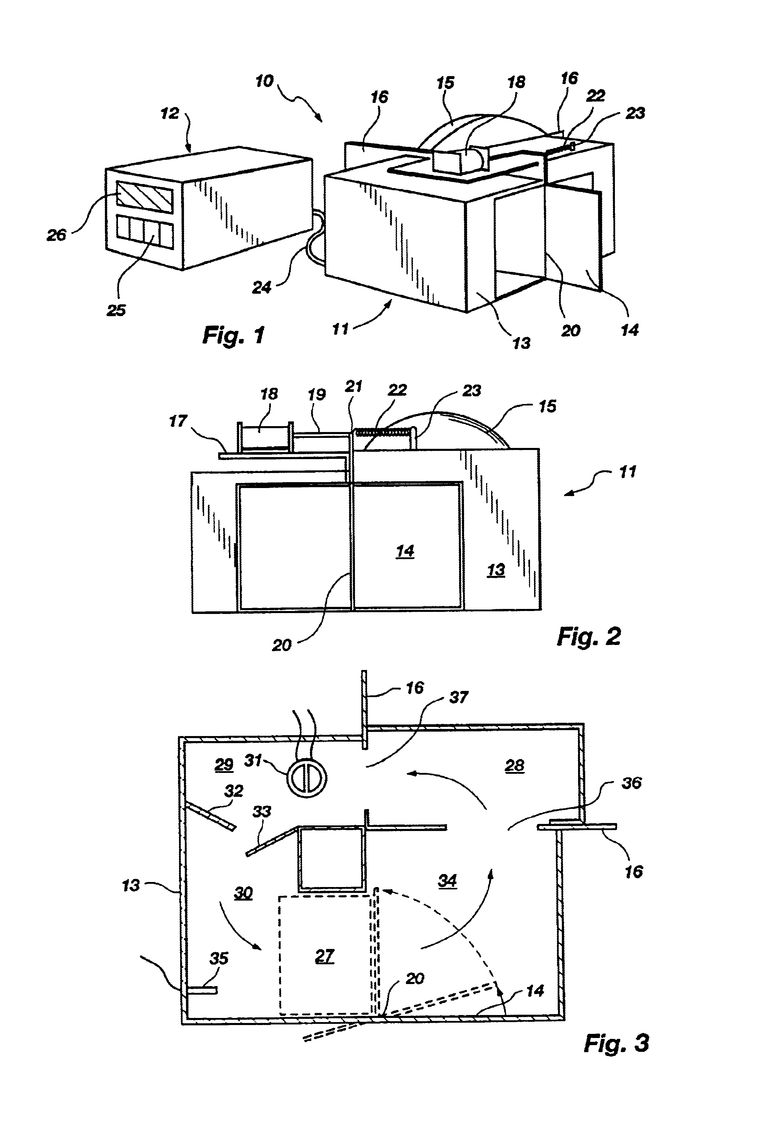
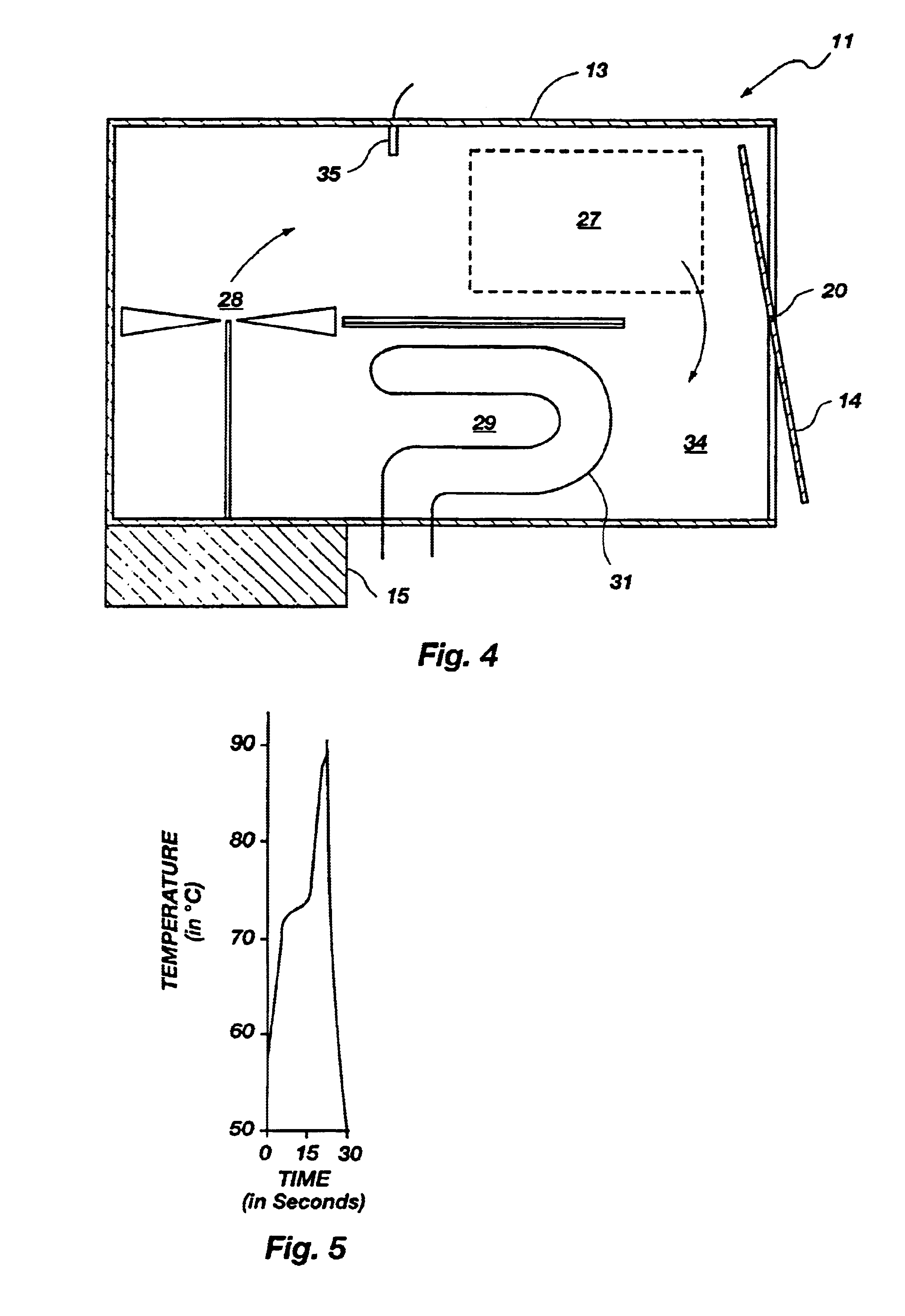
Shown in FIG. 8A is the general configuration of the housing 102 of the embodiment. The housing 102 rests on feet 104 (best seen in FIG. 8B) and functions to hold the other described structures in place and to isolate those structures which become hot from the surrounding environment. Included in FIG. 8A are input keys 25 and a display 26 as in the previously described apparatus 10. The previously described control structures can readily be modified or used as a pattern for a control means for use in the embodiment of FIGS. 8A-C.

As shown best in the cross sectional view of FIG. 8B, a sample chamber is designated by bracket 106. A lid 138 connected to the housing 102 by a hinge 131 can be opened to allow access to the sample chamber 106. The sample chamber 106 is preferably cylindrical in shape but can be of any shape or size required by the particular application.

The sample chamber 106 is lined with a black colored foam material 110 whose surface has light absorbing characteristics ...

example 2

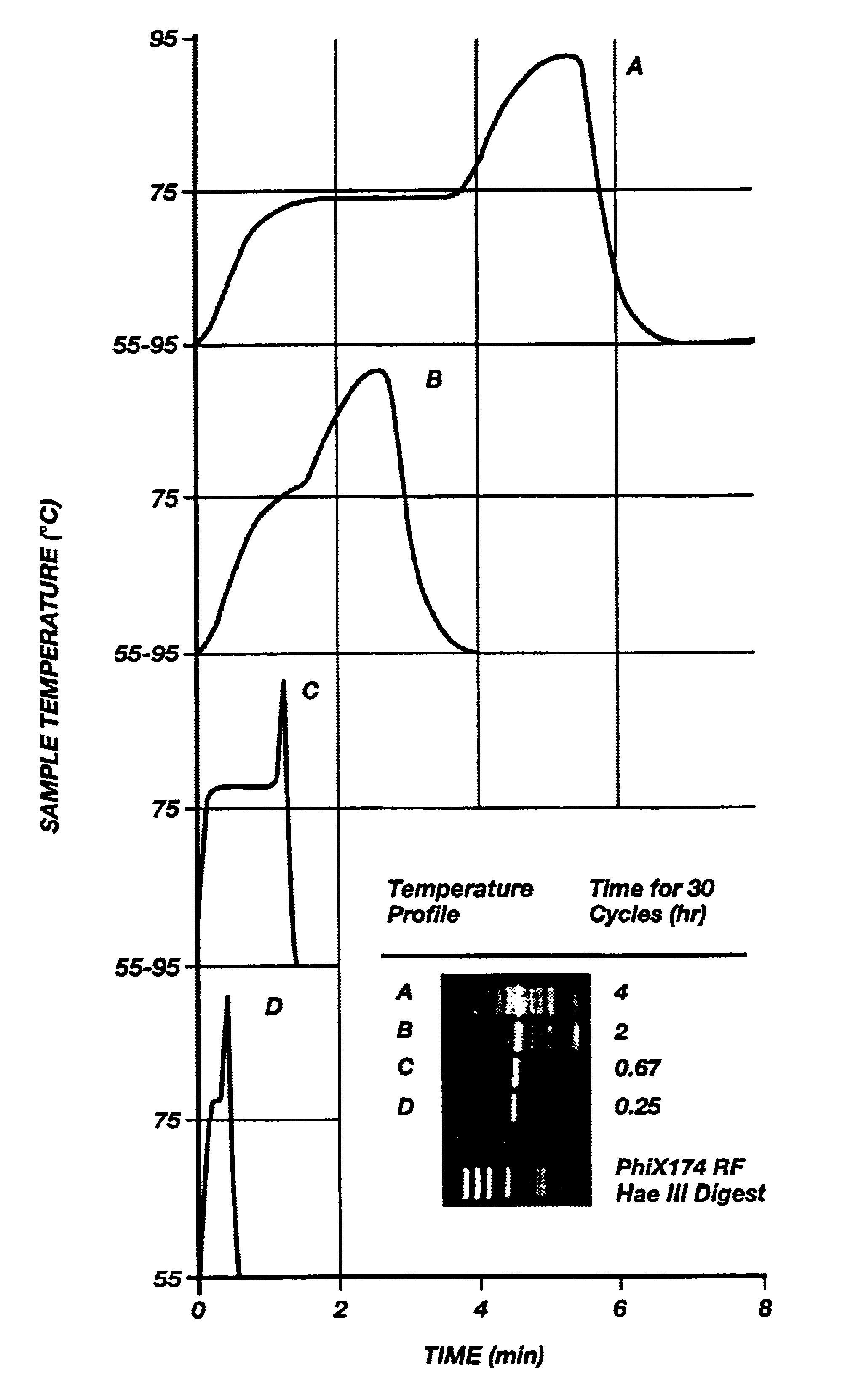
FIG. 9A shows the results of four different temperature / time profiles (A-D) and their resultant amplification products after thirty cycles (A-D). The profiles A and B in FIG. 9A were obtained using a prior art heating block device using the prior art microfuge tube. As can be seen in FIG. 9A, the transitions between temperatures are slow and many nonspecific bands are present in profiles A and B. Profile B shows improvement in eliminating some of the nonspecific bands (in contrast to profile A) by limiting the time each sample remains at each temperature thus indicating that shorter times produce more desirable results.

Profiles C and D were obtained using the apparatus of FIGS. 8A-B. As can be seen in FIG. 9A, amplification is specific and, desirably, even though yield is maximal in C (60 second elongation) it is still entirely adequate in D (10 seconds elongation).

The optimal times and temperatures for the amplification of a 536 bp fragment of .beta.-globin from human genomic DNA w...


PUM

PropertyMeasurementUnit
timeaaaaaaaaaa
timeaaaaaaaaaa
timeaaaaaaaaaa

Abstract

A thermal cycling method and device is disclosed. The device comprises a sample chamber whose temperature can be rapidly and accurately modulated over a range of temperatures needed to carry out a number of biological procedures, such a the DNA polymerase chain reaction. Biological samples are placed in glass micro capillary tubes and then located inside the sample chamber. A programmable controller regulates the temperature of the sample inside the sample chamber. Once a heating cycle is completed, the controller opens a door to the chamber for venting hot air out and cool ambient air is moved in. Temperature versus time profiles corresponding to optimum denaturation, annealing and elongation temperatures for amplification of DNA are achieved by the present invention.

Description

THE FIELD OF THE INVENTIONThis invention relates generally to apparatus for rapid control of the temperature of a liquid sample. More specifically, the present invention relates to thermal cycling apparatus for precisely controlling and rapidly varying the temperature of a sample repeatedly through a predetermined temperatures cycle.THE BACKGROUND ARTIn numerous areas of industry, technology, and research there is a need to reliably and reproducibly subject relatively small samples to thermal cycling. The need to subject a sample to repeated thermal cycles is particularly acute in biotechnology applications. In the biotechnology field, it is often desirable to repeatedly heat and cool small samples of materials over a short period of time. One such biological process that is regularly carried out is cyclic DNA amplification.Cyclic DNA amplification, using a thermostable DNA polymerase, allows automated amplification of primer specific DNA, widely known as the "polymerase chain react...

Claims


Application Information

Patent Timeline
Patent Type & Authority Patents(United States)
IPC IPC(8): B01L7/00C12M1/36C12M1/38G01N30/02G01N30/06G01N30/00G01N30/46
CPCB01L7/52B01L9/065B01L2200/147B01L2300/0838B01L2300/1827B01L2300/1844B01L2300/1872B01L2300/1883G01N30/02G01N30/06G01N27/447B01D15/34
Inventor WITTWER, CARL T.HILLYARD, DAVID R.
Owner THE UNIV OF UTAH
Why Eureka
Try Eureka