Catalyst systems

a catalyst and composition technology, applied in the field of catalyst compositions, can solve the problems of underutilization of the entire catalytic activity potential of the catalyst composition, ineffective or efficient use of catalyst deep within the inner partition wall, and inability to achieve catalyst operation temperature more quickly, reduce thermal mass, and achieve the effect of reducing the number of nitrogen oxide denitration or selective catalytic reduction

Active Publication Date: 2010-11-11
CORMETECH INC +1
View PDF6 Cites 1 Cited by
  • Summary
  • Abstract
  • Description
  • Claims
  • Application Information

AI Technical Summary

Benefits of technology

[0009]One feature and advantage of the present invention is that an embodiment of a catalyst body of the present invention may weigh less than heretofore known catalyst bodies while achieving similar amounts of selective catalytic reduction of nitrogen oxides.
[0010]Another feature and advantage of the present invention is that an embodiment of a catalyst body of the present invention weighing the same as heretofore known catalyst bodies will achieve greater levels of denitration or selective catalytic reduction of nitrogen oxides.
[0011]A further feature and advantage of the present invention is that an embodiment of a catalyst body of the present invention displays a catalyst having a lower thermal mass for reaching catalytic operating temperatures more quickly.
[0012]A still further feature and advantage of the present invention is that an embodiment of a catalyst body of the present invention demonstrates a reduced pressure drop sustained by the fluids caused to flow through the longitudinal flow channels, thereby reducing the energy expended for fluid flow through the catalyst body.

Problems solved by technology

The overall mechanical strengths and structural integrities of prior monolithic catalyst bodies have been limited by the inability to achieve a reduced inner wall thickness while maintaining adequate strength and porosity.
The strength requirements for SCR catalyst bodies have often resulted in the underutilization of the entire catalytic activity potential of the catalyst compositions due to a combination of a minimum inner wall thickness necessary for mechanical strength coupled with resultant mass transport limitations for diffusion.
As a result of these constraints, catalyst deep within the inner partition walls is not used as effectively or efficiently as catalyst near the surface of the inner partition walls.

Method used


Image

  • Catalyst systems
  • Catalyst systems
  • Catalyst systems

Examples


example 1

Prior Art

[0082]Example 1 describes a prior art honeycomb-like monolithic structural catalyst body. This example is provided to set forth a basis of comparison for the following examples of embodiments of the present invention.

[0083]The honeycomb-like monolithic structural catalyst body of Example 1 was produced by a generally utilized extrusion technique. The compositional parameters and physical properties of the catalytic body are summarized in Table 2. The catalytic body displayed a catalyst composition comprising 75.6% titania (TiO2), 8.9% tungsten trioxide (WO3), 3.4% vanadium pentoxide (V2O5), and 12.1% other components comprising SiO2, CaO, Al2O3, Fe2O3, SO4, and minor species.

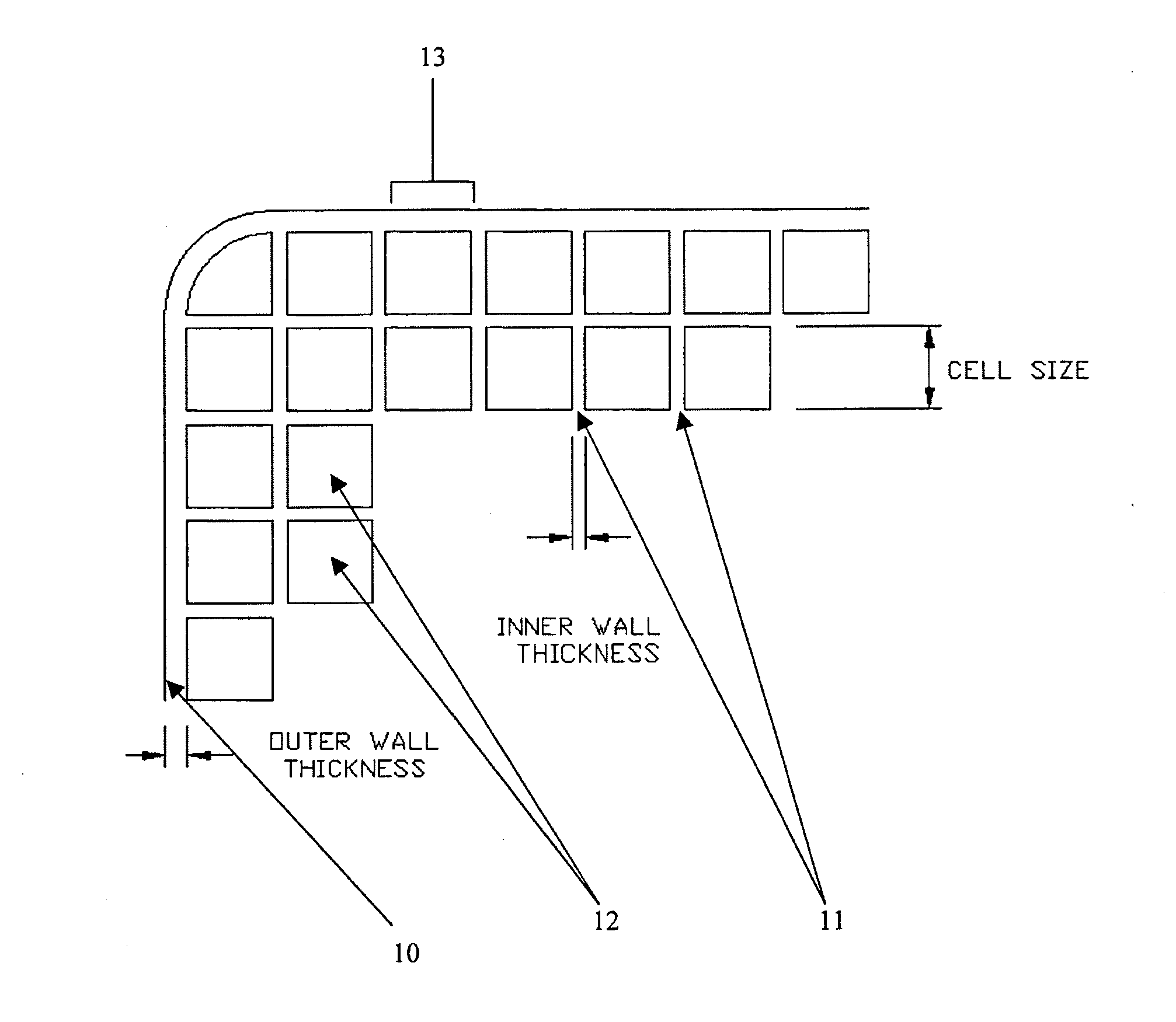
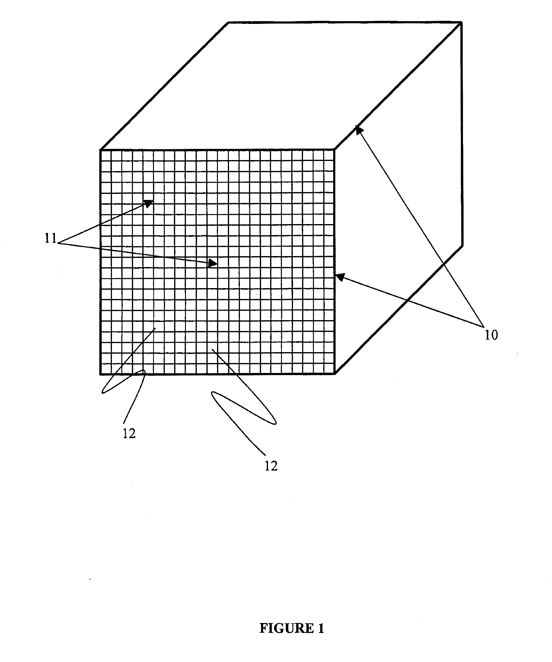
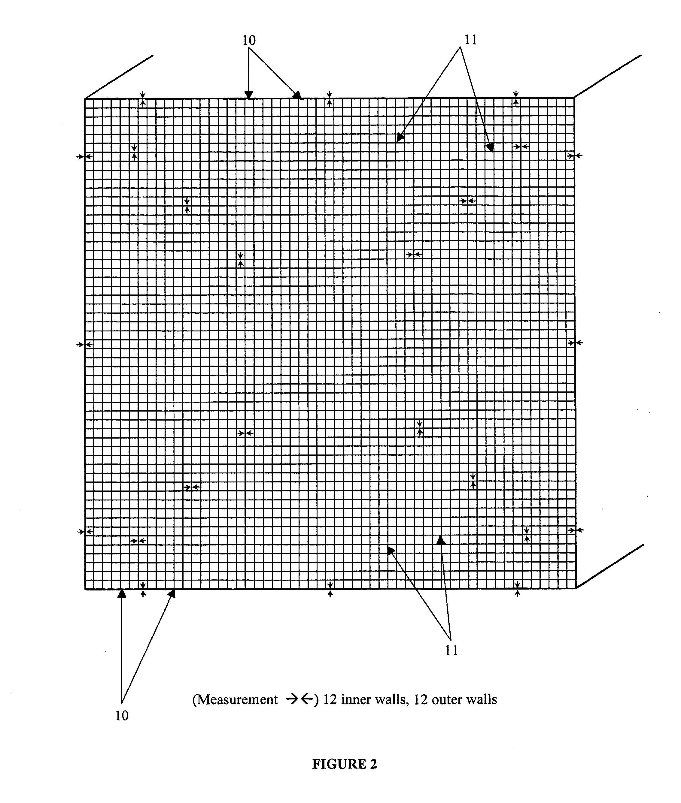
[0084]The thickness of the inner partition walls of the catalyst body was 0.27 mm while the thickness of the outer peripheral wall was 0.65 mm, the walls being measured in accordance with the twelve (12) point method previously described. The flow channels enclosed by the inner partition walls and outer...

example 2

[0090]A honeycomb-like monolithic structural catalyst body of the present invention was prepared by extrusion according to the method of described herein for producing a structural catalyst body of the present invention wherein energy loss was minimized by the use of a lubricant and die clogging was minimized by the use of a screen as described herein. The compositional parameters and physical properties of the catalytic body are summarized in Table 3. The catalytic body displayed a catalyst composition comprising 78.3% titania (TiO2), 7.7% tungsten trioxide (WO3), 3.5% vanadium pentoxide (V2O5), and 10.5% other comprising SiO2, CaO, Al2O3, Fe2O3, SO4, and minor species.

[0091]The thickness of the inner partition walls of the catalyst body was 0.21 mm while the thickness of the outer peripheral wall was 0.57 mm, the walls being measured in accordance with the twelve (12) point method previously described. The flow channels enclosed by the inner partition walls in were nominally squar...

example 3

[0101]A honeycomb-like monolithic structural catalyst body of the present invention was prepared by extrusion according to the method of described herein for producing a structural catalyst body of the present invention wherein energy loss was minimized by the use of a lubricant and die clogging was minimized by the use of a screen as described herein. The compositional parameters and physical properties of the catalytic body are summarized in Table 4. The catalytic body displayed a catalyst composition comprising 72.6% titania (TiO2), 19.2% tungsten trioxide (WO3), 0% vanadium pentoxide (V2O5), and 8.2% other components comprising SiO2, CaO, Al2O3, Fe2O3, SO4, and minor species.

[0102]The thickness of the inner partition walls of the catalyst body was 0.20 mm while the thickness of the outer peripheral wall was 0.56 mm, the walls being measured in accordance with the twelve (12) point method previously described. The flow channels enclosed by the inner partition walls and outer peri...


PUM

PropertyMeasurementUnit
thicknessaaaaaaaaaa
hydraulic diameteraaaaaaaaaa
thicknessaaaaaaaaaa

Abstract

The present invention provides monolithic structural catalysts. The catalysts have a thin wall structure and are advantageous for catalyzing reactions of gaseous fluid or liquid fluid molecules, such as the denitration or selective catalytic reduction (SCR) of nitrogen oxides (NOx) in combustion flue gases. In an embodiment, the honeycomb-like monolithic structural body includes catalytically active outer peripheral walls and a plurality of catalytically active thin-walled inner partition walls, the thin-walled inner partition walls adapted to enhance fluid flow through the monolithic catalytic body and to increase interaction of the fluid molecules with the catalyst body.

Description

FIELD OF THE INVENTION[0001]The present invention relates generally to catalyst compositions. An embodiment of the present invention provides a thin-walled honeycomb-like monolithic structural catalyst.BACKGROUND OF THE INVENTION[0002]The high toxicity of nitrogen oxides and their role in the formation of acid rain and tropospheric ozone have resulted in the imposition of strict standards limiting the discharges of these chemical species. To meet these standards, it is generally necessary to remove at least part of these oxides present in the exhaust gases from stationary or mobile combustion sources[0003]Denitration or selective catalytic reduction (SCR) technology is commonly applied to combustion-derived gases for removal of nitrogen oxides. The denitration reaction comprises the reaction of nitrogen oxide species in the gases, such as nitric oxide (NO) or nitrogen dioxide (NO2), with a nitrogen containing reductant, such as ammonia or urea, resulting in the production of nitroge...

Claims


Application Information

Patent Timeline
Patent Type & Authority Applications(United States)
IPC IPC(8): B01D53/56B01J27/055B01D53/86B01J35/04
CPCB01J35/04B01D2255/20707B01D2255/20723B01D2255/20776B01D2255/9202B01J35/1066B01D2257/404B01J23/22B01J23/30B01D53/8631B01D2255/9205
Inventor DIFRANCESCO, CHRIS E.ALTIZER, JAMES C.HASTINGS, THOMAS W.KASSMAN, EDWARD F.TREFZGER, CHRISTIAN
Owner CORMETECH INC
Why Eureka
Try Eureka