Pressure relief device assemblies

a pressure relief device and assembly technology, applied in the direction of functional valve types, containers, transportation and packaging, etc., can solve the problems of reducing the efficiency of venting, affecting the ability of the explosion panel to quickly and completely open, and increasing the cost of manufacturing the explosion panel

Inactive Publication Date: 2004-09-21
BS&B SAFETY SYST LTD
View PDF17 Cites 46 Cited by
  • Summary
  • Abstract
  • Description
  • Claims
  • Application Information

AI Technical Summary

Benefits of technology

Accordingly, the present invention is directed to pressure relief devices, assemblies, and components that obviate one or more of the limitations and disadvantages of prior art pressure relief systems. The advantages and purposes of the invention will be set forth in part in the description which follows, and in part will be obvious from the description, or may be learned by practice of the invention. The advantages and purposes of the invention will be realized and attained by the elements and combinations particularly pointed out in the appended claims.

Problems solved by technology

In many cases, the additional weight of a vacuum support will inhibit the ability of the explosion panel to quickly and completely open.
In addition, the inclusion of a vacuum support may increase the costs associated with manufacturing the explosion panel.
Higher mass typically results in a lower vent efficiency.
These slits may, however, reduce the vacuum resistance of the explosion panel.
When the slits are cut into the explosion panel, the structural integrity of the explosion panel is weakened.
Thus, the explosion panel may fail in the area of the slits when exposed to a negative pressure differential.
Even if the explosion panel is exposed to a negative pressure differential that does not cause the panel to fail, repeated pressure cycles may fatigue the tabs and thereby alter the pressure differential at which the explosion panel will open.
However, the operating conditions of the plastic bolts have a direct impact on the material strength of the bolt.
Varying climate conditions may alter the material strength of the plastic bolts and, thus, the pressure differential at which the explosion panel will open.
A plastic bolt may also fail at a much higher load under dynamic deflagration venting conditions making prediction of behavior unreliable.
When a pressure relief device, such as, for example, a rupture disk, an explosion panel, or a vacuum support, is exposed to the predetermined pressure differential, a portion of the pressure relief device will typically tear to create an opening.
However, when the pressure relief device experiences a pressure differential that is significantly greater than the predetermined opening pressure differential or a sustained turbulent flow, the hinge area has a tendency to tear, thereby allowing the pressure relief device to fragment.

Method used


Image

  • Pressure relief device assemblies
  • Pressure relief device assemblies
  • Pressure relief device assemblies

Examples


Embodiment Construction

Reference will now be made in detail to the present preferred embodiments of the invention, examples of which are illustrated in the accompanying drawings. Wherever possible, the same reference numbers will be used throughout the drawings to refer to the same or like parts.

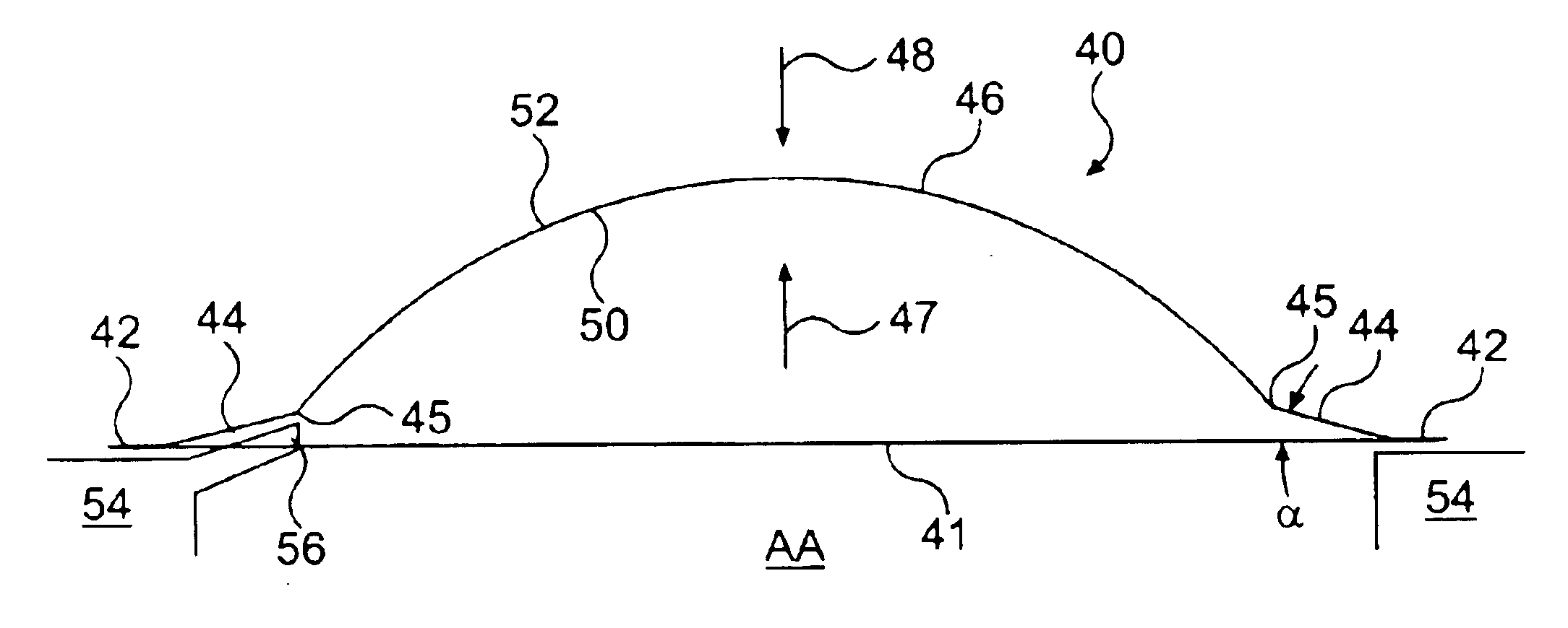
One aspect of the present invention has application in all types of pressure relief devices. Such devices include, but are not limited to, rupture disks, explosion panels, and vacuum supports. In this respect, the present invention is directed to a method of reducing the likelihood of fragmentation in such a pressure relief device. This reduced fragmentation potential is achieved by increasing the area over which the opening stresses are applied when the pressure relief device is activated.

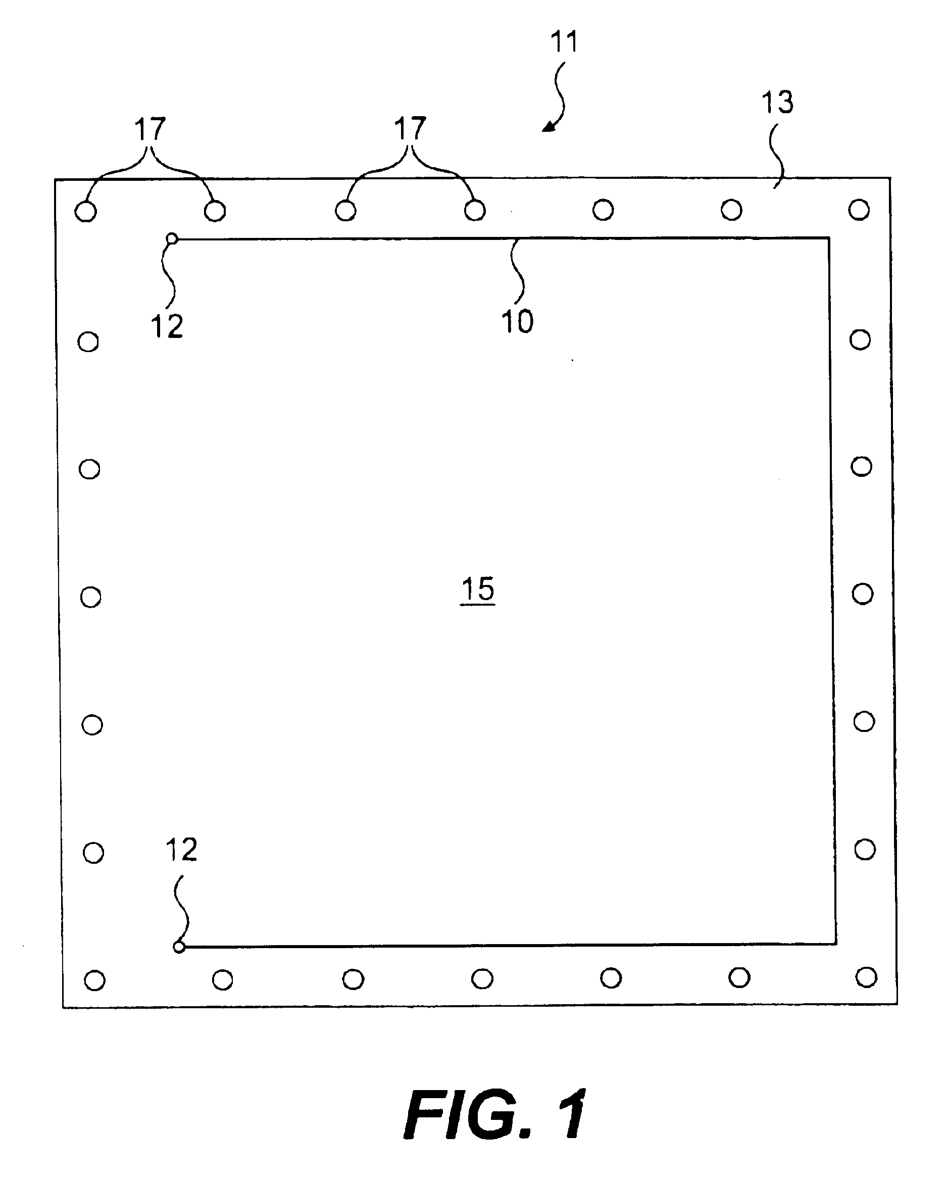
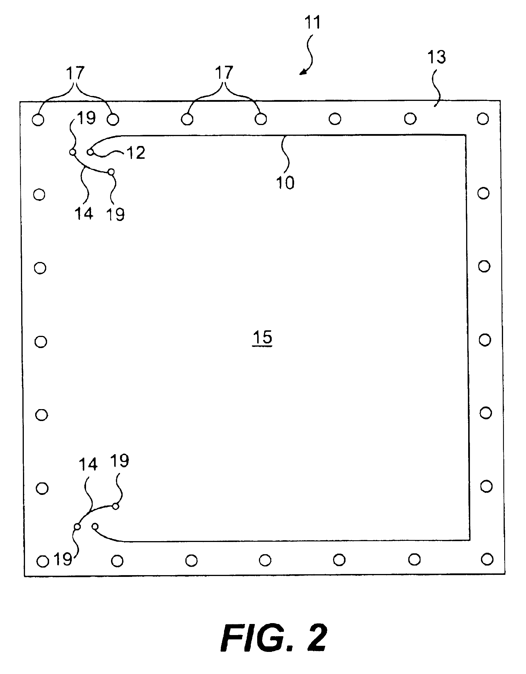
An exemplary explosion panel is illustrated in FIG. 1 and is designated generally by reference number 11. As shown, explosion panel 11 includes a flange 13 and a central section 15. Flange 13 may have a square shape as illustrat...


PUM

PropertyMeasurementUnit
angleaaaaaaaaaa
angleaaaaaaaaaa
shapeaaaaaaaaaa

Abstract

The present invention is directed to pressure relief devices and to corresponding pressure relief assemblies that have improved vacuum resistance, improved fragmentation resistance, and/or improved burst control while maintaining low mass. The pressure relief device includes a substantially flat flange section and a domed section. The domed section may include a transitional line that defines a change in the shape of the domed section. The pressure relief device may also include a bracket for securing or aligning a domed section to a flange section. The pressure relief device may further include a stress distribution feature that is disposed transversely to a line of weakness in the domed section. The pressure relief assembly may include a fastener having a wire that is configured to break and release the pressure relief device when subject to a predetermined tensile load.

Description

BACKGROUND OF THE INVENTION1. Field of the InventionThis invention relates to pressure relief devices, assemblies, and components, as well as methods of forming the same.2. Background of the InventionMany types of pressure relief devices exist in the art. These pressure relief devices may include, for example, explosion panels, rupture disks, vacuum supports, and valves. An explosion panel is one type of pressure relief device that is typically used to provide emergency pressure relief under deflagration conditions in an environment such as, for example, a silo or a dust collector. An explosion panel may be subject to both a positive pressure differential and a negative pressure differential. In a positive pressure differential, the pressure within the environment is greater than the external pressure. In a negative pressure differential, the external pressure is greater than the pressure within the environment. In most circumstances, it is desirable for the explosion panel to open ...

Claims


Application Information

Patent Timeline
Patent Type & Authority Patents(United States)
IPC IPC(8): F16K17/02F16K17/16
CPCF16K17/162Y10T29/494Y10T403/11Y10T137/1744Y10T137/1669Y10T137/1692Y10T137/1729F16B2200/63
Inventor FARWELL, STEPHEN P.KLEIN, GREGORY P.BRAZIER, GEOFFREY C.PLUNKETT, GARY M.
Owner BS&B SAFETY SYST LTD
Why Eureka
Try Eureka