
Device for exposing a face of a panel

a panel and face technology, applied in the field of devices for exposing the face of panels, can solve the problems of short circuits, single shutters that do not enable short exposure times, and the image reproduction accuracy is degraded, so as to achieve the effect of improving the exposure of panels

Inactive Publication Date: 2004-09-28
AUTOMA TECH
View PDF8 Cites 2 Cited by
  • Summary
  • Abstract
  • Description
  • Claims
  • Application Information

AI Technical Summary

Benefits of technology

"The present invention provides a device for improving panel exposure in a way that allows for different materials to be exposed without compromising the sensitivity of the material. The device includes two shutters that can be moved to different positions to adjust the window size and the speed at which the light source moves. This allows for both short and long exposure times, and ensures uniform exposure over the entire panel. The device can be controlled and adjusted in real-time, making it easy to use with different materials and power sources. The speed of the shutters is constant throughout their displacement, and the device can be adjusted to control the amount of energy received by the material without needing to change the displacement speed of the shutters. The displacement control means can adjust the window size by acting on the displacement means at all times throughout the panel processing."

Problems solved by technology

When the material is underexposed, subsequent development takes place poorly, and in particular the polymerization of the photosensitive material is irregular, often leading to tracks on the printed circuit that are too fine or even that are interrupted; in the opposite case of overexposure, the fidelity with which the image is reproduced is degraded, in particular by the tracks becoming wider than the desired width, which can lead to certain tracks touching one another, thereby leading to short circuits.
Nevertheless, those devices having a single shutter do not enable short exposure times to be obtained with shutter displacement having a level of accuracy that is sufficient and repeatable.
In the first case, the plane shutter generally performs a go-and-return stroke past the light source, and the zone of the panel that is exposed first ends up by being exposed for longer since it is also the zone to be masked last, which means that exposure is not uniform over the entire surface.
Nevertheless, it is necessary to increase the speed of rotation of the shutter quite considerably in order to obtain exposure times that are very short, particularly when they are shorter than one second, and that leads to technical difficulties in implementation.
Consequently, for short exposure durations, the device does not enable satisfactory repeatability to be guaranteed between two exposures, whether in terms of rotation speeds or in terms of the precision with which the shutter can be stopped.

Method used


Image

  • Device for exposing a face of a panel
  • Device for exposing a face of a panel
  • Device for exposing a face of a panel

Examples


first embodiment

In a first embodiment shown in FIGS. 3 and 4, the shutters slide relative to each other. A first shutter, e.g. 16'A co-operates with a second shutter 16'B via first displacement means comprising a slideway 32'A, a rack or any other known means for generating movement in translation preferably being fixed on the second shutter 16'B. In this embodiment, the displacement means comprise on one hand, for the first shutter 16'A, the slideway 32'A fixed to the second shutter 16'B and actuatable by first initialization means 36'A specific thereto, and on the other hand, for the second shutter 16'B, second displacement means comprising, for example, a rodless pneumatic actuator 32'B fixed to the stationary frame 14 and over which the shutter 16'B is moved in translation in the plane P under drive from second initialization means 36'B which are specific thereto.

Control means 34' are connected to the first and second initialization means 36'A and 36'B of the respective shutters 16'A and 16'B. ...

second embodiment

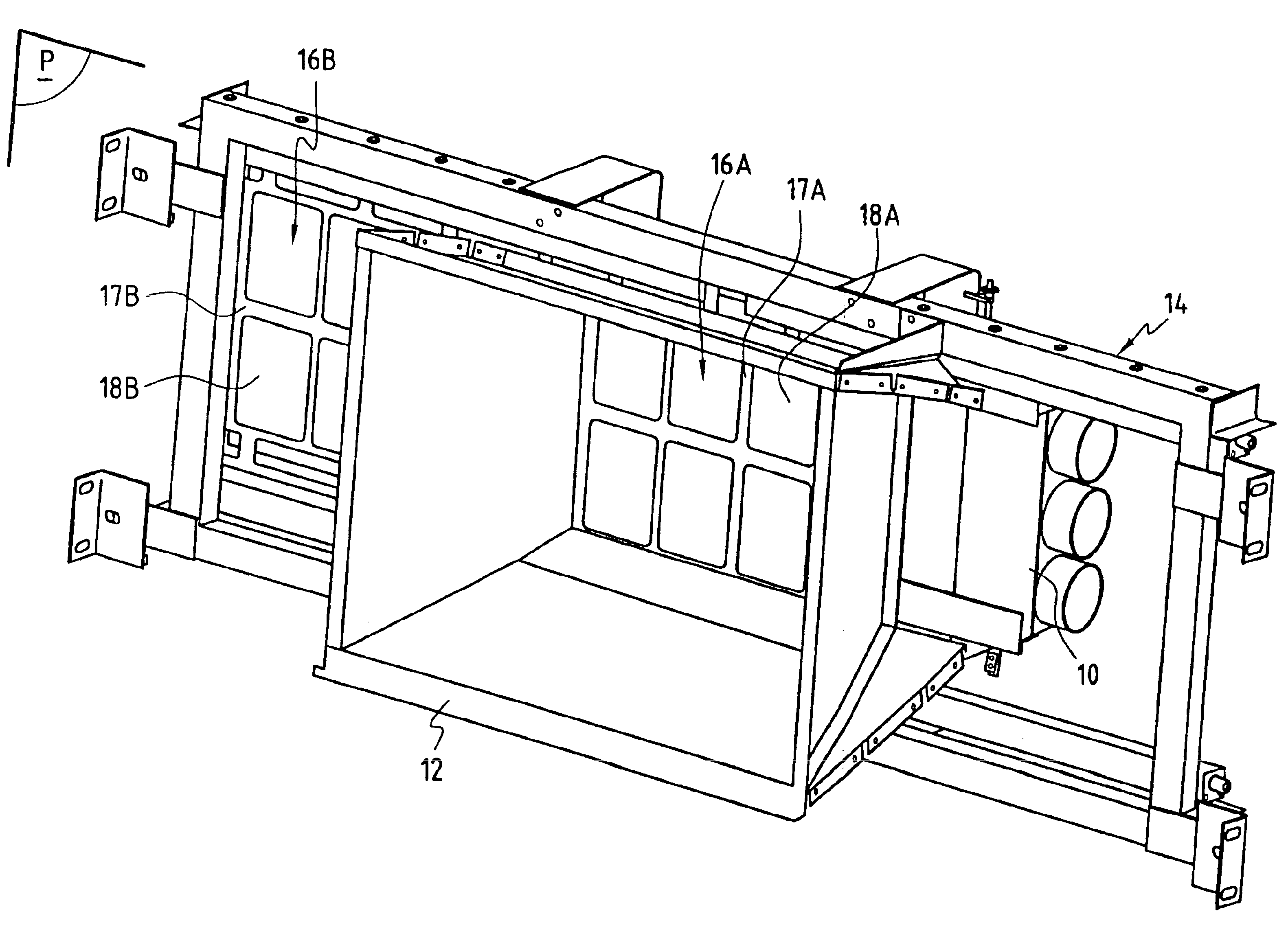
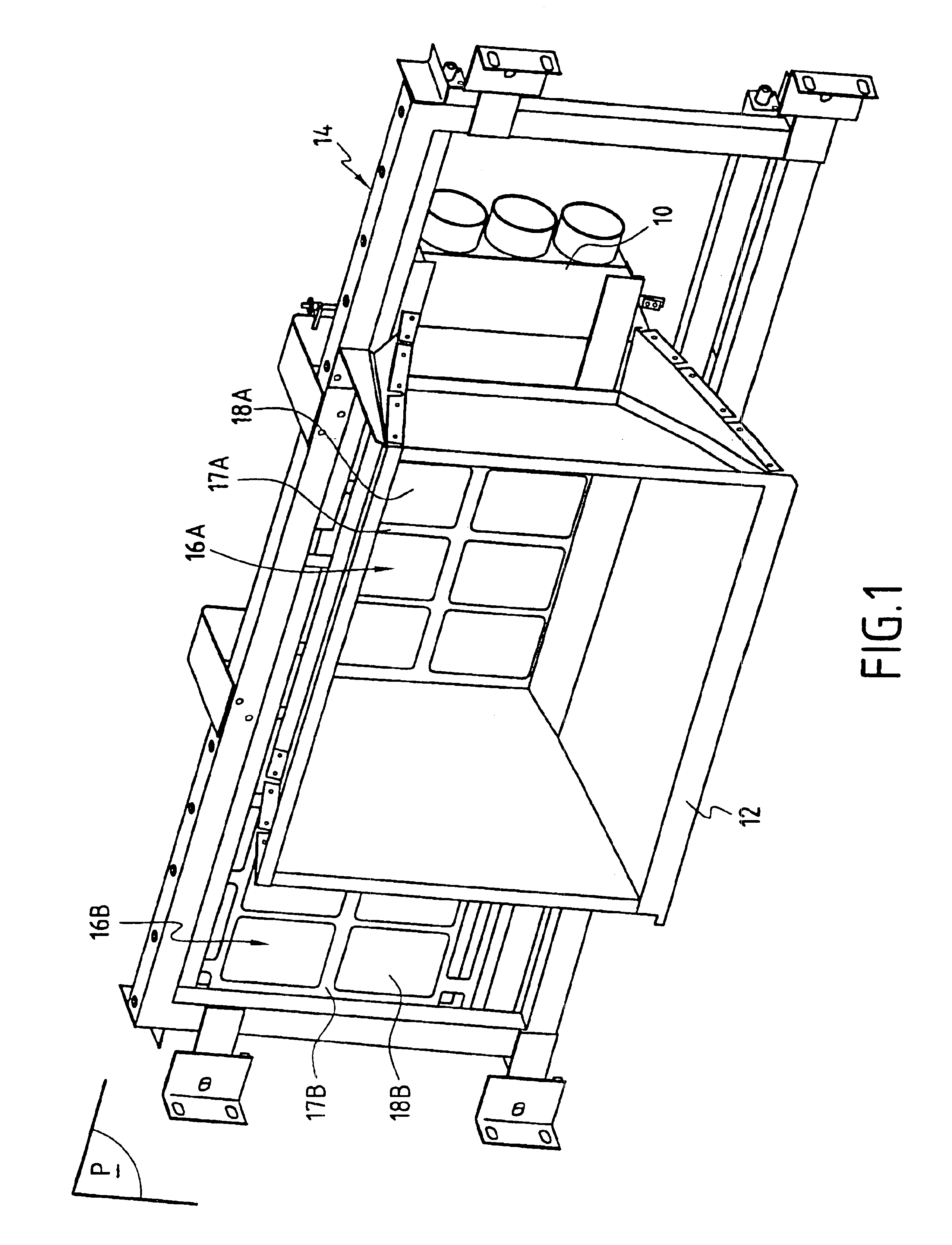
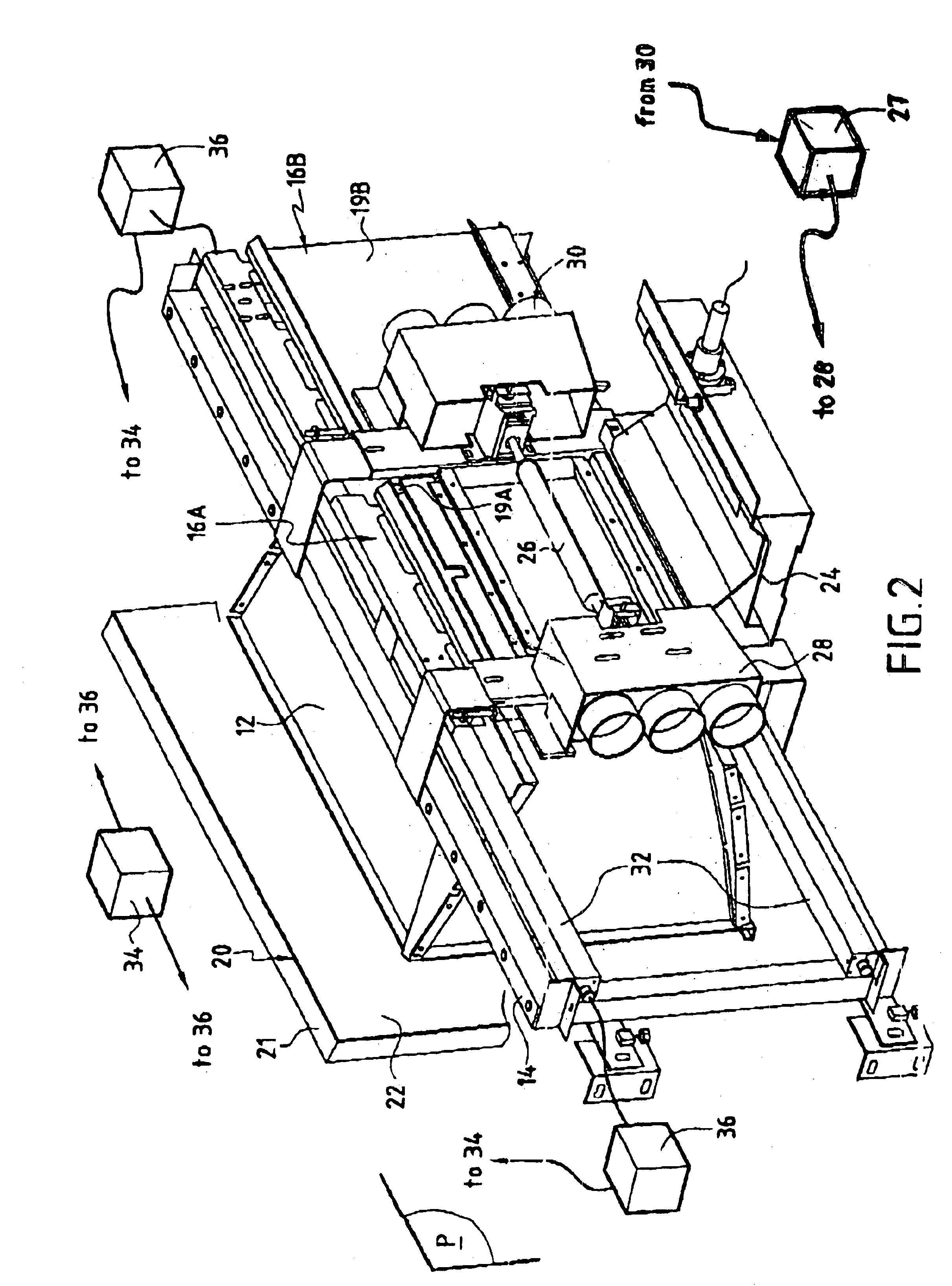
In a second embodiment shown in FIGS. 5 and 6, each of the shutters 16A and 16B slides individually past the light box assembly 10. In this embodiment, both shutters 16A and 16B are identical and each of them necessarily moves at the same speed V past the light source 26 (see FIG. 2). This embodiment is comparable with the preceding embodiment and differs only in the relative displacement of the shutters 16A and 16B and in the displacement means. The shutters 16A and 16B have the same properties of withstanding the heat to be removed, having a strength member of refractory material (not shown) and with heat being removed via a respective side 19A, 19B coated in light reflecting material.

Thus, starting from the closed position shown in FIG. 5 in which, by way of example, the first shutter 16A closes the entire light box 10 while the second shutter 16B is on the right-hand side of the device, the two respective edges 40A and 40B of the shutters are touching.

Each of the shutters 16A, 1...


PUM

PropertyMeasurementUnit
temperaturesaaaaaaaaaa
speedaaaaaaaaaa
timeaaaaaaaaaa

Abstract

The invention provides apparatus for exposing a face of a panel, in particular a printed circuit panel, the device including a light source. The device further comprising:two moving shutters suitable for masking said light source, each of said shutters presenting a respective edge, said edges together defining a window through which a light zone is generated on said face of the panel to be exposed;means for displacing said shutters in a plane lying between said light source and said panel; andcontrol means for controlling the displacement of said shutters in such a manner that both shutters move past said face of the panel at substantially the same speed and in the same direction.

Description

The present invention relates to a device for exposing at least one face of a panel, in particular a printed circuit panel, the device comprising a light source and means for holding said panel facing said light source.Such devices serve in particular to make printed circuits from a panel coated in photosensitive material with artwork being put in front of the panel, said artwork carrying tracks to be generated on the printed circuit. A light beam then serves to expose the entire panel either by scanning successively over said surface or else by globally exposing the surface as a whole.The photosensitive material which generally comprises a dry film or ink needs to receive a precise quantity of light energy that is constant over its entire area in order to ensure good polymerization of the photosensitive material, thereby guaranteeing the final quality of the printed circuit. When the material is underexposed, subsequent development takes place poorly, and in particular the polymeri...

Claims


Application Information

Patent Timeline
Patent Type & Authority Patents(United States)
IPC IPC(8): G03F7/20H05K3/00
CPCG03F7/2002H05K3/00
Inventor VIBET, GILLESCUEVAS, MANUEL
Owner AUTOMA TECH
Learn More