Micromachine switch
a micro-machine switch and switch technology, applied in the field of micro-machine switches, can solve the problems of leakage signal increase, small loss, low cost and power consumption, etc., and achieve the effect of increasing the switching speed and stabilizing the switching operation
- Summary
- Abstract
- Description
- Claims
- Application Information
AI Technical Summary
Benefits of technology
Problems solved by technology
Method used
Image

Examples
first embodiment
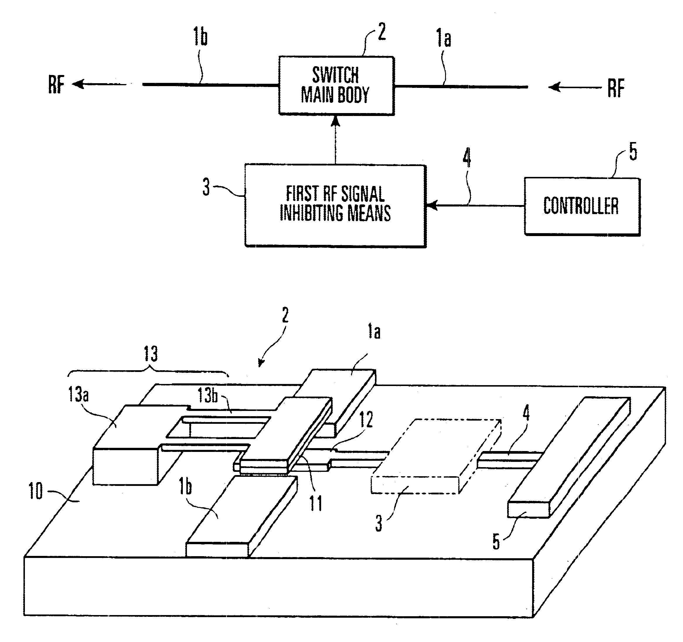
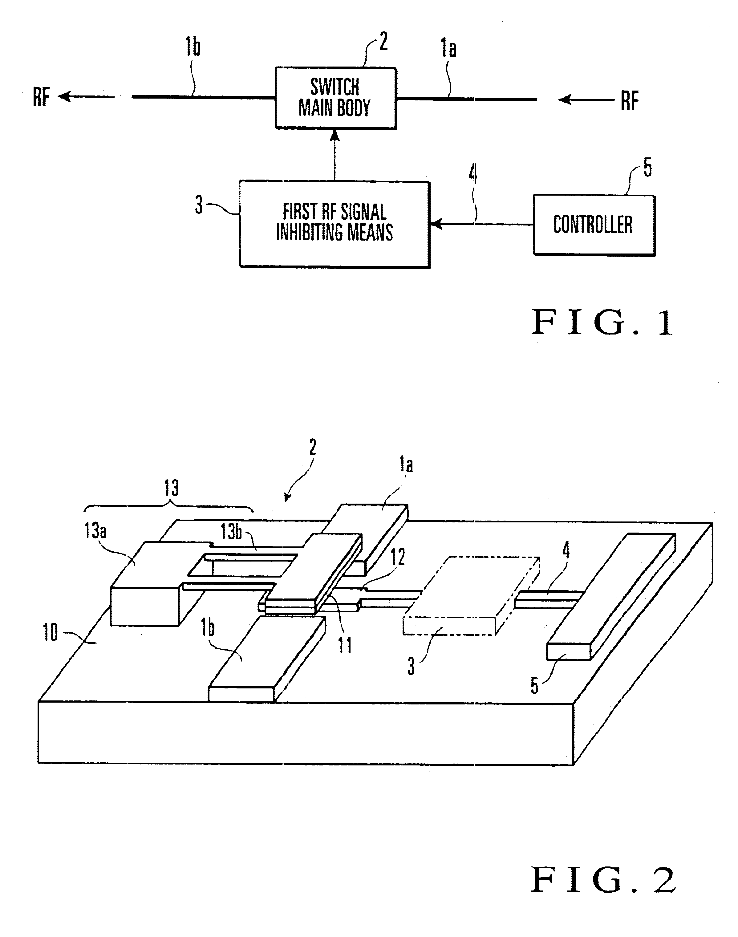
FIG. 1 is a block diagram showing the overall arrangement of a micromachine switch according to the first embodiment of the present invention. FIG. 2 is a perspective view showing the first arrangement of a switch main body in FIG. 1.
As shown in FIG. 2, RF signal lines 1a and 1b are formed on a substrate 10 at a small gap.
A contact 11 is supported by a support means 13 above the gap between the RF signal lines 1a and 1b so as to freely contact the RF signal lines 1a and 1b.
The support means 13 is constituted by a post 13a and arm 13b. The post 13a is formed on the substrate 10 to be spaced apart from the RF signal lines 1a and 1b. The arm 13b extends from the upper portion of the side surface of the post 13a to the space above the gap between the RF signal lines 1a and 1b. The contact 11 is attached to the lower surface of the distal end portion of the arm 13b.
A control electrode 12 is formed at the gap between the RF signal lines 1a and 1b on the substrate 10, i.e., at a position i...
second embodiment
FIG. 8 is a block diagram showing the overall arrangement of a micromachine switch according to the second embodiment of the present invention. FIG. 9A is a circuit diagram showing an arrangement of the micromachine switch, and FIG. 9B is a plan view of the arrangement.
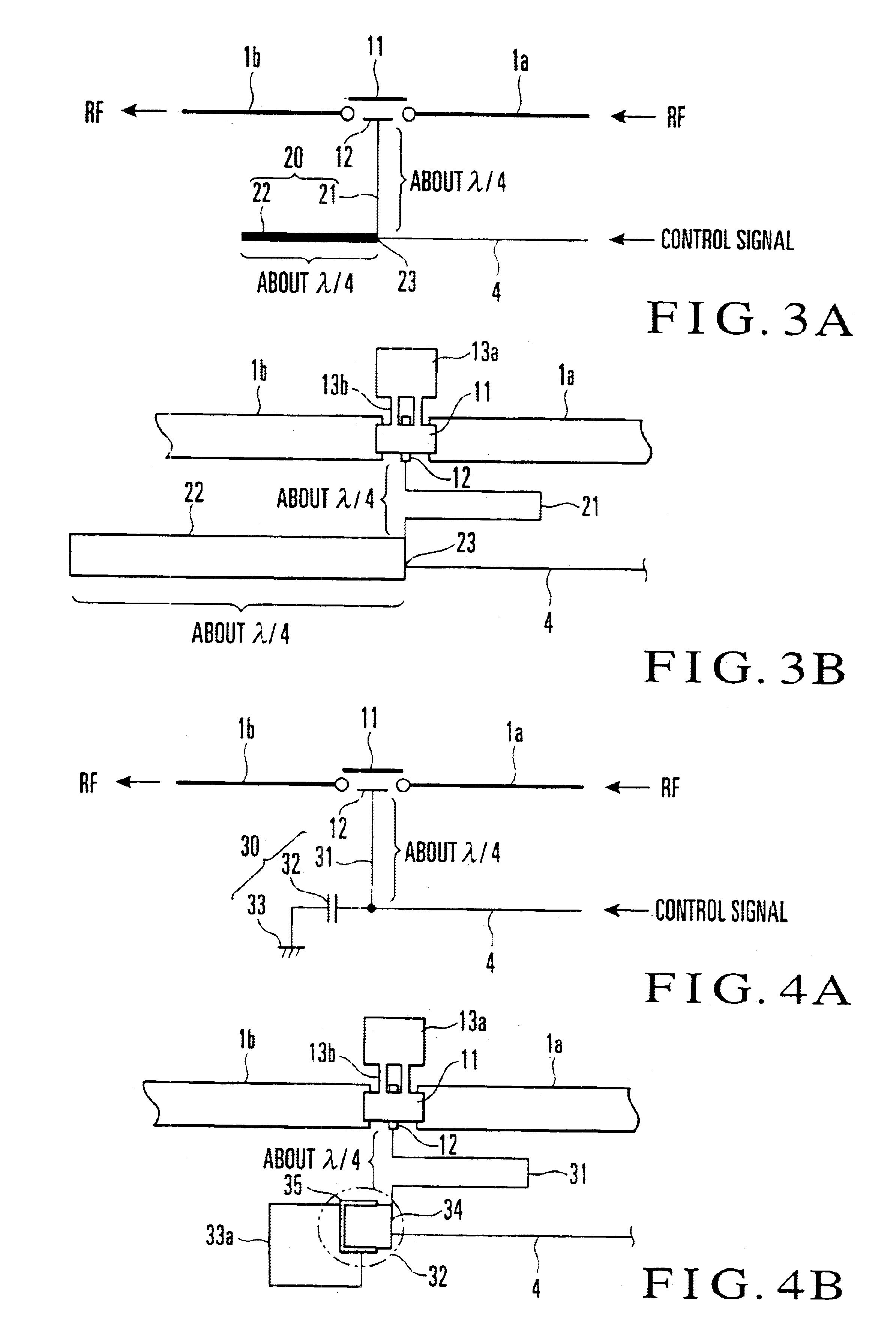
The micromachine switch shown in FIGS. 9A and 9B is obtained by grounding a contact 11 of the micromachine switch shown in FIGS. 3A and 3B through a support means 13', a filter 20a serving as a second RF signal inhibiting means 3a, and a second control signal line 4a.
The support means 13' has the same arrangement as the support means 13 shown in FIG. 2 except that it is made of a conductive member, i.e., a conductor or semiconductor.
The filter 20a has the same arrangement as the filter 20 shown in FIG. 3A and is constituted by a high-impedance .lambda. / 4 line 21a and low-impedance .lambda. / 4 line 22a. One end of the high-impedance .lambda. / 4 line 21a is connected to the support means 13', and the other end is connecte...
PUM
 Abstract
Description
Claims
Application Information
 - R&D Engineer
- R&D Manager
- IP Professional
- Industry Leading Data Capabilities
- Powerful AI technology
- Patent DNA Extraction
Browse by: Latest US Patents, China's latest patents, Technical Efficacy Thesaurus, Application Domain, Technology Topic.
© 2024 PatSnap. All rights reserved.Legal|Privacy policy|Modern Slavery Act Transparency Statement|Sitemap