Eureka AIR delivers breakthrough ideas for toughest innovation challenges, trusted by R&D personnel around the world.

Bearing device and method of manufacturing the bearing device

Inactive Publication Date: 2004-10-26
KOYO SEIKO CO LTD
View PDF8 Cites 3 Cited by
  • Summary
  • Abstract
  • Description
  • Claims
  • Application Information

AI Technical Summary

Benefits of technology

According to the bearing device of the present invention, the surface roughness of the inner peripheral surface of the cylindrical portion is set to a value corresponding to a life ratio regulated with respect to a bearing device having a standard life. Therefore, when the caulking jig is abutted on the inner peripheral surface of the cylindrical portion in order to caulk the cylindrical portion on the outer end surface of the inner ring of the bearing, an amount of abrasion powder generated therein is restrained despite a strong contact of the caulking jig with the inner peripheral surface of the cylindrical portion. Consequently, a life of the bearing is favorably lengthened by a decreased amount of the abrasion powder which invades inside of the bearing.

Problems solved by technology

An invasion of such abrasion powder inside of the bearing may shorten a life thereof.
Under the circumstances described above, a lubricant oil used to restrain the friction adheres to the abrasion powder, which makes it extremely difficult to remove the abrasion powder which has once invaded inside of the bearing.
Also, such a laborious work as eliminating the oil-adhered abrasion powder from inside of the bearing becomes unnecessary.

Method used


Image

  • Bearing device and method of manufacturing the bearing device
  • Bearing device and method of manufacturing the bearing device
  • Bearing device and method of manufacturing the bearing device

Examples


Embodiment Construction

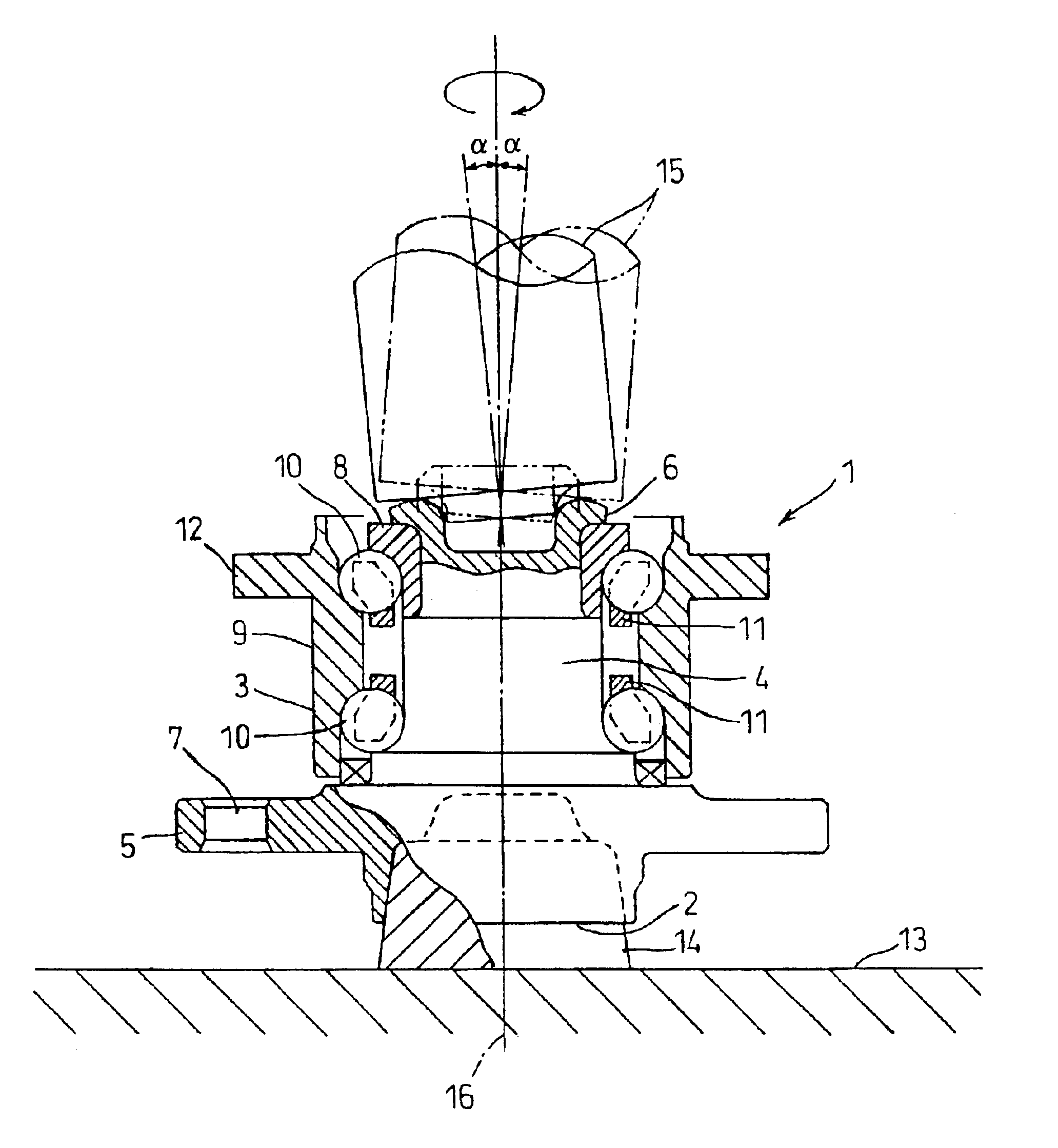
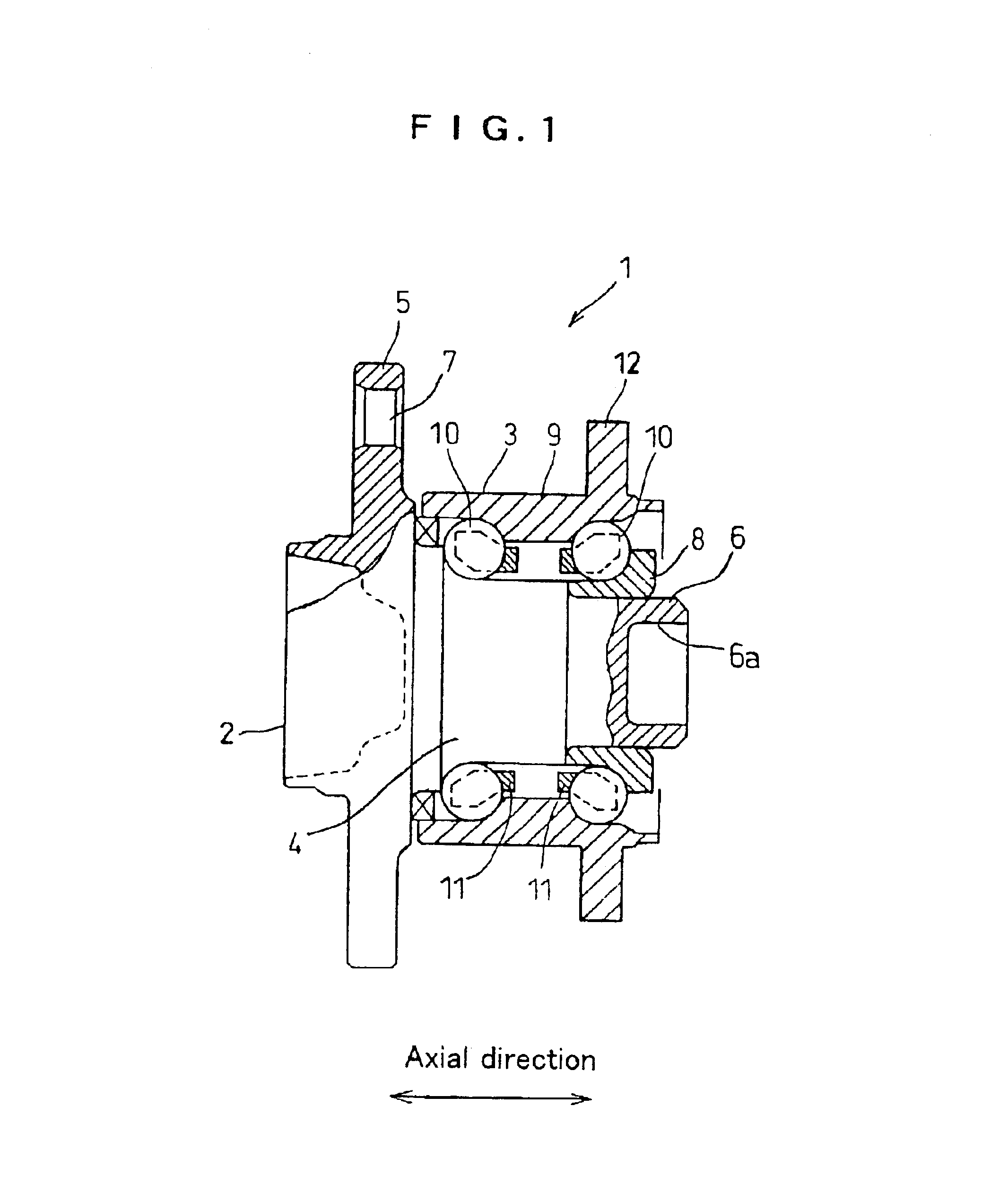
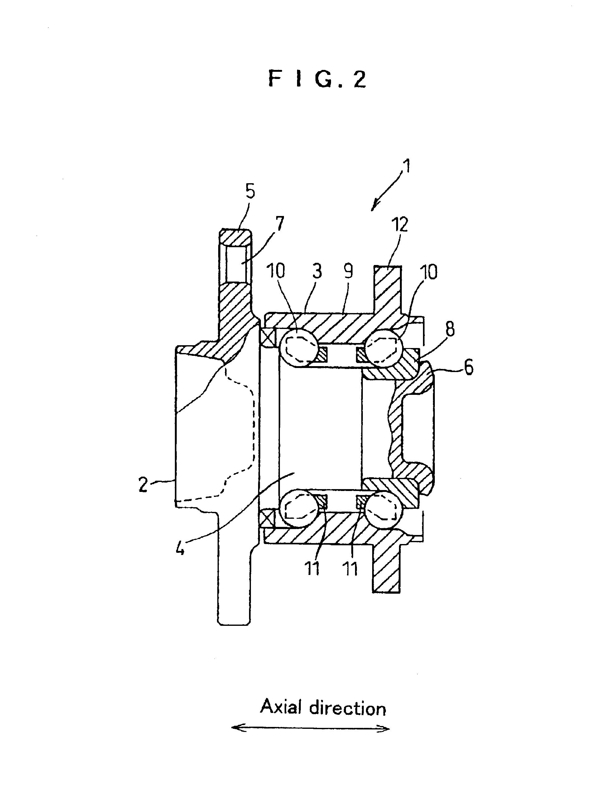
FIGS. 1 through 4 relate to a hub unit according to the best mode of the present invention. FIG. 1 is a longitudinal sectional view of a hub unit prior to a caulking work. FIG. 2 is a longitudinal sectional view of a hub unit which has been caulked. FIG. 3 is a longitudinal sectional view of a hub unit provided for explanation of a caulking work. FIG. 4 is a chart showing a life comparison (R) between an actually measured hub unit and a standard hub unit with respect to a surface roughness (Rz).

Referring to these figures, a vehicle-use hub unit 1 comprises a hub wheel 2, a double row angular ball bearing 3 with vertex of contact angles outside of bearing as an example of a rolling bearing.

The hub wheel 2 has a shaft body 4 and a flange 5.

The shaft body 4, in a free end side thereof, has a cylindrical portion 6 having an inner peripheral surface which axially extends.

The flange 5 of the hub wheel 2 is provided radially outward on an outer periphery of the shaft body 4 and has some bo...


PUM

PropertyMeasurementUnit
Surface roughnessaaaaaaaaaa
Mean roughnessaaaaaaaaaa

Abstract

A bearing device comprising a shaft body having an axially cylindrical portion in a free end side thereof and a rolling bearing fitted around an outer peripheral surface of the shaft body, wherein the cylindrical portion is bent and deformed radially outward by a rolling caulking to be caulked thereby on an outer end face of an inner ring of the rolling bearing, and a surface roughness of the inner peripheral surface of the cylindrical portion is set to 12.5 mum or less by a ten-point mean roughness (Rz).

Description

This invention relates to a bearing device in which a rolling bearing is fitted around an outer periphery of a shaft body such as a hub unit for vehicles and a method of manufacturing the same.BACKGROUND TECHNIQUESuch a vehicle-use hub unit as a bearing device generally has a structure wherein a double row rolling bearing is fitted around an outer periphery of a shaft body of a hub wheel so as not to come off.The shaft body of the hub wheel is provided in a free end side thereof with a cylindrical portion used for the bearing not to come off. The cylindrical portion, formed by a turning work, is bent and deformed radially outward by a caulking jig, thereby being caulked on an outer end surface of an inner ring which the bearing equips to constitute a caulked portion. The bearing is prevented from coming off the hub wheel by the caulked portion, and simultaneously, the inner ring of the bearing is preloaded from the caulked portion.When the cylindrical portion is caulked on the outer...

Claims


Application Information

Patent Timeline
IPC IPC(8): B60B27/00F16C35/063F16C35/04F16C37/00
CPCB60B27/0005B60B27/001B60B27/0042B60B27/0094F16C35/063F16C37/00B60B27/0084Y10T29/49696F16C19/184F16C43/04F16C2326/02
Inventor TODA, KAZUTOSHIKASHIWAGI, SHINICHIROUISHII, TOMOHIROMITARAI, TADASHITOMITA, DAISAKU
Owner KOYO SEIKO CO LTD
Why Eureka
Eureka Blog
Learn More