
Optical recording medium

a technology of optical recording and recording medium, applied in the field of optical recording medium, can solve the problems of difficult multi-level recording, difficult to perform multi-level recording in many levels, and difficult to change the reflection level during regeneration in five levels or mor

Inactive Publication Date: 2004-10-26
TDK CORPARATION
View PDF4 Cites 11 Cited by
  • Summary
  • Abstract
  • Description
  • Claims
  • Application Information

AI Technical Summary

Benefits of technology

The inventor has diligently conducted research on an optical recording medium and discovered a recording method that performs multilevel recording on this optical recording medium, and also verified that this recording method can perform high-density multilevel recording in five levels or more on this optical recording medium. Furthermore, the inventor has performed various types of experiments and found that stipulating the material properties of the optically transparent substrate and the coefficient of thermal conductivity and film thickness of the reflecting film was important for thermal diffusion. In addition, the inventor has found that if a dye whose thermal decomposition exceeds a range extending over 100.degree. C. or more is used, favorable recording becomes possible extending over the time when the laser irradiation time goes from short to long and / or extending over the time when the laser irradiation power goes from low to high. Even further, the inventor has found that if a dye whose thermal decomposition starts at 300.degree. C. or less is used, high sensitive recording becomes possible through which the inventor has completed the present invention.
These effects were present due to heat that occurred while recording in optical recording mediums used up to the present. However, it is assumed that even greater effects would more easily occur due to recording marks being placed adjacent in a linear direction in order to improve the recording density in the multilevel recording method.

Problems solved by technology

Multilevel recording is, however, difficult when attempting to reduce the recording marks smaller than the beam diameter of a converged laser used for recording and reading.
Consequently, in the method in Japanese Patent Laid-Open Publication No. Hei. 10-134353, the non-recording level and the recording level depend on a relationship of whether or not a recording exists and are not suitable for recording in many levels.
If, however, the length of the recording marks are shortened to increase the recording density, it becomes difficult to perform multilevel recording in many levels, in particular in five levels or more, using a method that modulates the power of the laser to change the recording mark width.
In other words, changing the recording power makes it difficult to change the reflection level during a regeneration in five levels or more,
For this case, if the recording mark length was 1.6 .mu.m or less, it is difficult to perform multilevel recording in five levels or more using a conventional method that changes the laser power.
The absolute value of the absorbance change is presumed to be very small for this optical recording medium however and has not yet attained practical use.
In this optical recording method there is a problem in which the coloring density state cannot be read in live levels of more when irradiating and scanning laser light.
If, however, there is rapid decomposition of the dye material during multilevel recording, decomposition of the dye will suddenly begin when a specified laser irradiation time or irradiation power is exceeded making it difficult to control the recording in many levels required for multilevel recording.
For example, if the diffusion of the thermal energy is insufficient for an optical recording medium such as a CD-R, unfavorable effects will occur such as deformation of the substrate or the guide tracks cut into the substrate.
Using a material with a coefficient of thermal conductivity of 300 k / W.multidot.m.sup.-1.multidot.K.sup.-1 as the reflecting film material in the present invention or setting the thickness of the reflecting film to 50 nm or less results in excessive heat causing deformation of the substrate or the channels cut into the substrate used to guide the laser as well as deformation of the protective film on the reflecting film leading to degradations in the recording signals.

Method used


Image

  • Optical recording medium
  • Optical recording medium
  • Optical recording medium

Examples


example 1

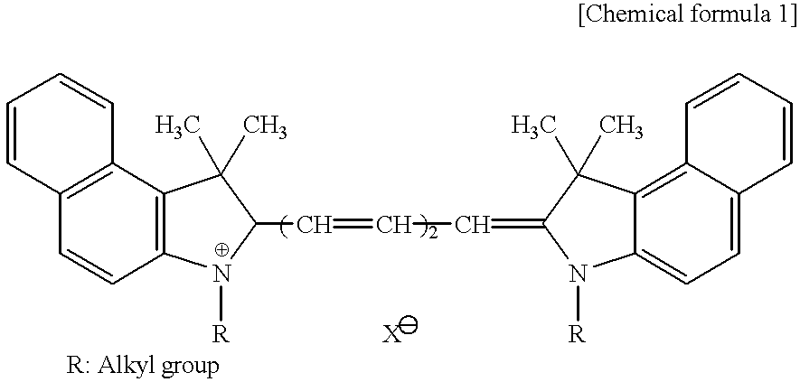
Cyanine dye was dissolved into a fluoridated alcohol to prepare a 2% coating solution used to form a recording layer. A spin coat method in which the rpm was varied from 200 rpm up to 5000 rpm was used to coat this coating solution onto the surface of a pre-groove side of an optically transparent substrate with a diameter of 120 mm and a thickness of 1.2 mm that was composed of a polycarbonate resin (Teijin Kasei Inc.; Panlight AD5503) whereon a spiral-shaped pre-groove (track pitch: 1.6 .mu.m, pre-groove width 0.35 .mu.m, pre-groove depth 0.18 .mu.m) was formed by means of injection molding. This process formed an organic dye recording layer approximately 200 nm thick from the bottom of the inside of the pre-groove. The glass transition temperature of the polycarbonate was 140.degree. C.

Next, a sputtering method was utilized to form an Ag (coefficient of thermal conductivity of silver is 427 k / W m.sup.-1.multidot.K.sup.-1 ; chronological table of science) reflecting film approximat...

example 2

An optical recording medium was produced in the same manner as example 1 and multilevel recording performed although the film thickness of the Ag reflecting film was changed to 100 nm. The recording conditions were identical to example 1. Jitter values of the recorded signals were measured in the same manner.

example 3

An optical recording medium was produced in the same manner as example 1 and multilevel recording performed although the reflecting film material was changed to Au (coefficient of thermal conductivity of gold is 318 k / W.multidot.m.sup.-1.multidot.K.sup.-1 ; chronological table of science) The recording conditions were identical to example 1. Jitter values of the recorded signals were measured in the same manner.


PUM

PropertyMeasurementUnit
Tgaaaaaaaaaa
Tgaaaaaaaaaa
thicknessaaaaaaaaaa

Abstract

An optical recording medium is provided with a recording layer and a reflecting film on an optically transparent substrate. The principal component of the recording layer is a dye. Virtual recording cells are assumed within grooves on the recording layer and recording marks with five different levels or more of increasing size are formed on each of the virtual recording cells by modulating the irradiation time of the laser beam in five levels or more in correspondence to the information to be recorded. The reflectance of the virtual recording cells modulates in many levels and the reflection level of the reading laser beam during regeneration is changed in five levels or more. The optically transparent substrate is made of a plastic with a glass transition point (Tg) of 160° C. or less. The reflecting film is a metal with a coefficient of thermal conductivity of 300 k / W.m<-1>.K<-1 >or more and a film thickness of 50 nm or more.

Description

1. Field of the inventionThe present invention relates to an optical recording medium that switches either the irradiation time or the irradiation power of a laser beam in many levels in correspondence to data used in the recording, irradiates the recording layer with the laser beam and then records the data in multiple levels.2. Related ArtA great deal of research has been carried out related to methods to record multiple pieces of data in signals with identical length by switching the depth of a regeneration signal (modulation factor of reflection signal) in many levels in contrast to methods to record data by changing the length of a regeneration signal (length of the modulated part of the reflection signal) in many levels with conventional optical recording mediums such as CD-R or DVD-R which are provided with recording layers and reflecting films, in this order, on an optically transparent substrate.According to this optical recording method, because it is possible to record mu...

Claims


Application Information

Patent Timeline
Patent Type & Authority Patents(United States)
IPC IPC(8): G11B7/013G11B7/24G11B7/005G11B7/0045G11B7/00G11B7/248G11B7/247G11B7/125G11B7/24085G11B7/246G11B7/2467G11B7/2472G11B7/249G11B7/2492G11B7/253G11B7/2533G11B7/2534G11B7/257G11B7/2575G11B7/258G11B7/259G11B7/2595
CPCG11B7/00455G11B7/126G11B7/24G11B7/24085G11B7/246G11B7/0052Y10T428/21G11B7/2467G11B7/2472G11B7/248G11B7/2492G11B7/2533G11B7/2534G11B7/2575G11B7/259G11B7/2595G11B2007/24612G11C13/04
Inventor ARIOKA, HIROYUKISUNOHARA, HIDEKI
Owner TDK CORPARATION
Learn More