Bio-metric smart card, bio-metric smart card reader and method of use

a biometric and smart card technology, applied in the field of credit card security, can solve the problems of increasing fraud in the industry, affecting the security of transactions, and affecting the accuracy of transactions, and achieve the effect of increasing transaction security

Inactive Publication Date: 2004-11-09
AUDLEM
View PDF10 Cites 109 Cited by
  • Summary
  • Abstract
  • Description
  • Claims
  • Application Information

AI Technical Summary

Benefits of technology

In general, the present invention is a system for increasing transaction security across existing credit card processing infrastructure. A user bio-metric sensor device is integrated into a credit or debit "smart card". A display unit provides a key, preferably encrypted, upon successful utilization of the sensor device. Included in the key generation mechanism is an indicator of the transaction number or other sequential count indicative of card use. An authorization service decrypts the key in a manner at least partially dependent upon a second sequential count maintained in sync with the first count to determine whether the use is authorized. A separate reader may be similarly configured to read existing smart cards utilizing the process the present invention.
In one embodiment, the present invention is a smart card style apparatus including a bio-metric sensor providing the user an authentication data input for proving the user is authorized to use the account number, a transaction counter for tracking authorized device access events, a processor in electrical communication with the user authenticator and counter, wherein the processor is programmed to generate a security key in response to authentication data received via the sensor, and a display unit to display the security key on the face of the card. The security key is derived at least in part from the contents of the counter. In another embodiment, the present invention is configured as a portable reader for reading and authorizing purchases using existing smart cards. The present invention may also be configured as a peripheral device to a computer system.
According to the present invention, a method of securely authorizing a transaction utilizing an account comprises confirming an authorized use of an account card via a bio-metric sensor, maintaining a first count indicative of a number of instances of such authorized uses, generating a security key in a manner at least partially dependent upon the count, transmitting the security key to an authorizing authority, processing the security key at the authorizing authority, maintaining a second count indicative of a number of transmissions received by the authorizing authority for the account, confirming that the security key was generated by an authorized user at least in part through use of the first count and the second count, and authorizing the transaction if the security key is validated.

Problems solved by technology

Despite these advances, the industry remains burdened by a considerable fraud problem.
Credit card theft and fraud accounts for billions of dollars in damages a year in the U.S. alone, with billions more being lost overseas.
Sub-thumbnail sized photos on cards are often too small for careful examination by store clerks, and like holograms, cannot be viewed during online or telephone-based transactions.
And smart cards provide no new security features unless used across a new breed of card-reading infrastructure, which will cost hundreds of millions of dollars to install.
Moreover, like the other new technologies described above, smart cards do not address online and telephonic sales scenarios wherein the merchant lacks the ability to examine the actual card.
Perhaps most importantly, since smart cards are not compatible with the existing card-reading infrastructure they do not address the near term needs of the industry and the massive on-going losses caused by fraudulent use.
In the above-described available transaction process, while recent security advances do provide some crime protection, there is still far more opportunity than desirable for deception and fraud.
Specifically, if the card is lost or stolen the thief or finder of the lost card might use the card for fraudulent purchases.
Also, if a thief finds or steals a receipt or similar record listing the card number and other card information found in field 112, that information might be fraudulently used for online or telephonic transactions.

Method used


Image

  • Bio-metric smart card, bio-metric smart card reader and method of use
  • Bio-metric smart card, bio-metric smart card reader and method of use
  • Bio-metric smart card, bio-metric smart card reader and method of use

Examples


Embodiment Construction

The following description is provided to enable any person skilled in the art to make and use the invention and sets forth the best modes contemplated by the inventor for carrying out the invention. Various modifications, however, will remain readily apparent to those skilled in the art, since the basic principles of the present invention have been defined herein specifically to provide a bio-metric smart card, bio-metric smart card reader and method of use. Any and all such modifications, equivalents and alternatives are intended to fall within the spirit and scope of the present invention.

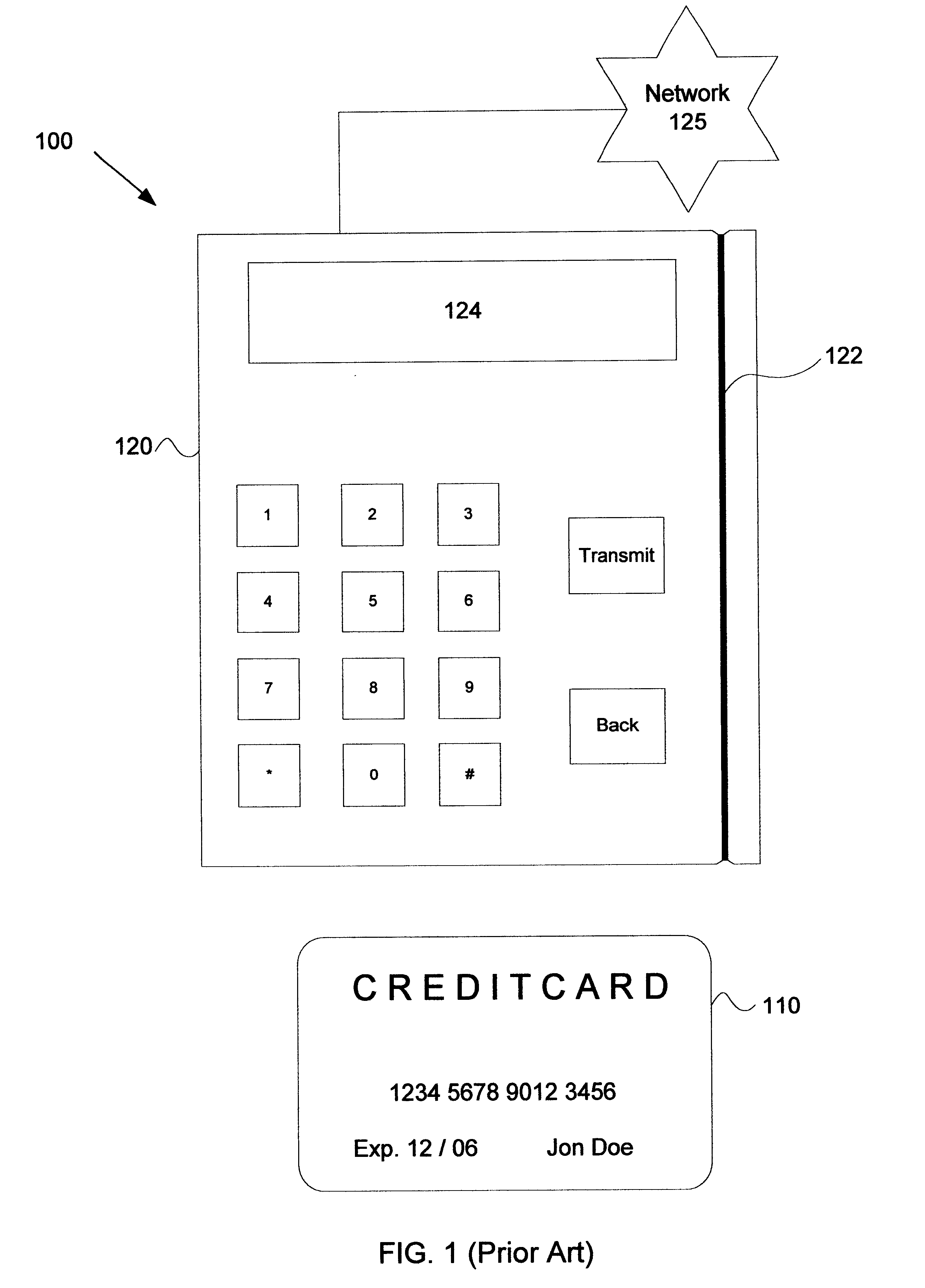
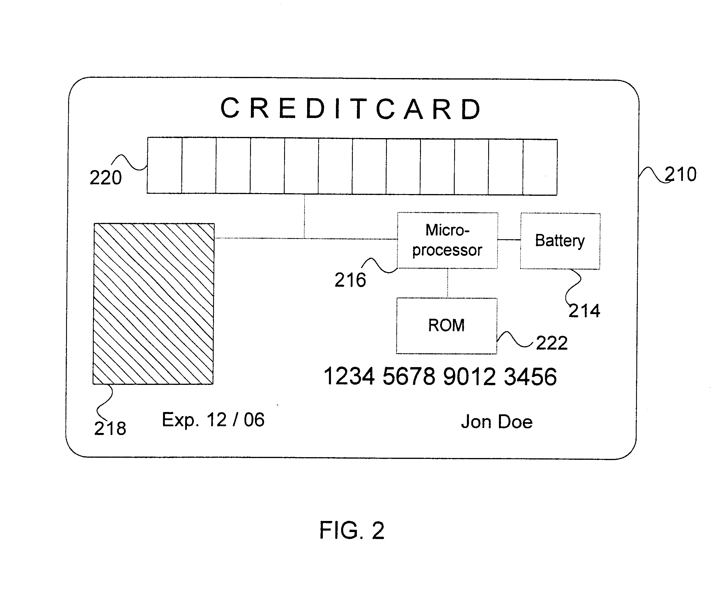
One embodiment of the present invention is illustrated in FIG. 2. In this embodiment a bio-metric smart card 210 is shown. The bio-metric smart card 210 preferably has substantially the same shape and form factor as available plastic credit and debit cards such as card 110 in FIG. 1, although card 210 might be thicker as needed to accommodate newly-introduced internal components. On a front surfa...


PUM


Abstract

A system for increasing transaction security across existing infrastructure is provided. A user bio-metric sensor device is integrated into a credit or debit card. A display unit provides a key, preferably encrypted, upon successful utilization of the sensor device. Included in the key generation mechanism is an indicator of the transaction number or other sequential count indicative of card use. An authorization service decrypts the key in a manner at least partially dependent upon a second sequential count maintained in sync with the first count to determine whether the use is authorized.

Description

BACKGROUND OF THE INVENTION1. Field of the InventionThe present invention relates generally to the field of credit card security, and more particularly to a bio-metric smart card, a bio-metric smart card reader and a method of use for the card and reader.2. Description of the Related ArtRecent innovations have brought significant security-related advances to the credit card, debit card, and consumer banking industries. In the 1980s, holographic images were introduced and included on plastic card faces to deter the manufacture of counterfeit cards. More recently, some cards have been adapted to include a photograph of the authorized user, thereby obviating the need for a purchaser to present separate identification and decreasing the likelihood of fraud. Most recently, smart cards, also known as personal data cards or chip cards, which include a memory chip integral with the card, now provide additional security features.Despite these advances, the industry remains burdened by a cons...

Claims


Application Information

Patent Timeline
Patent Type & Authority Patents(United States)
IPC IPC(8): G05B19/04G05B19/042G07C9/00G07F7/10
CPCG05B19/0425H04L9/0866G06Q20/341G06Q20/3415G06Q20/385G06Q20/40145G06Q20/4097G07C9/00087G07F7/0886G07F7/1008G05B2219/24162G05B2219/24167G05B2219/25192G07C2009/00095G05B2219/23342G07C9/26G07C9/257Y04S40/20
Inventor MCGREGOR, CHRISTOPHER M.MCGREGOR, TRAVIS M.MCGREGOR, D. SCOTT
Owner AUDLEM
Why Eureka
Try Eureka