Stiff metal hub for an energy storage rotor

a technology of energy storage rotor and metal hub, which is applied in the direction of mechanical equipment, manufacturing tools, couplings, etc., can solve the problems of high centrifugal force, high radial and hoop stress in the outermost composite rim, and metal hubs often do not experience radial growth commensurate with the size of the rim

Inactive Publication Date: 2004-11-16
BEACON POWER LLC
View PDF19 Cites 28 Cited by
  • Summary
  • Abstract
  • Description
  • Claims
  • Application Information

AI Technical Summary

Problems solved by technology

High rotational operating velocities, however, produce extremely high centrifugal forces, which produce high radial and hoop stresses in the outermost composite rim.
However, metal hubs often do not experience radial growth commensurate with, or of the same magnitude as, the deforming composite rim.
Consequently, the composite rim separates from the hub, which produces potentially deleterious vibrations.
However, composite hubs as a rule are not sufficiently stiff to produce a critical velocity that exceeds design operating speeds.
As a composite rim separates from a hub, holidays, or gaps, in the tight interference fit appear between the hub and the composite rim, causing undesirable and potentially deleterious vibrations.
Such vibrations are detrimental to the operation of the flywheel assembly.
Moreover, if they occur at the natural, or resonant, frequency of the flywheel assembly and/or the component parts of the flywheel assembly, these vibrations could seriously damage or altogether destroy the flywheel assembly.
However, with dished member hubs, having a lower modulus than the composite ring, the flywheel is less rig...

Method used


Image

  • Stiff metal hub for an energy storage rotor
  • Stiff metal hub for an energy storage rotor
  • Stiff metal hub for an energy storage rotor

Examples


Embodiment Construction

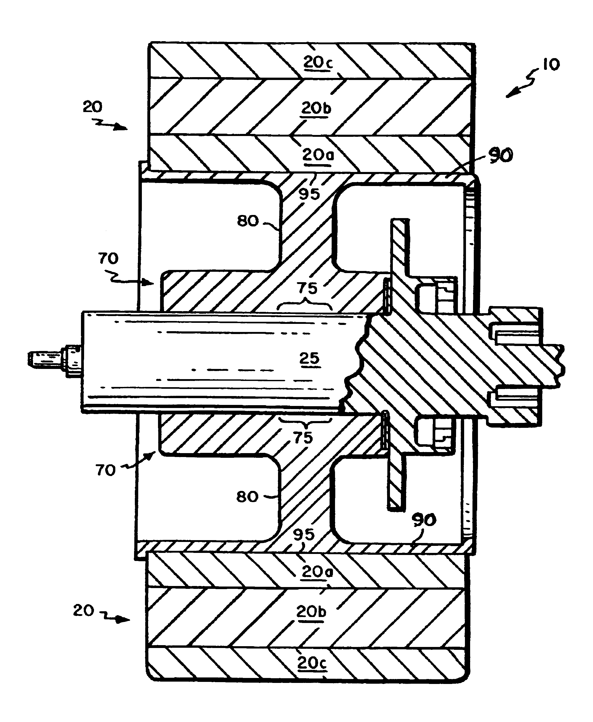
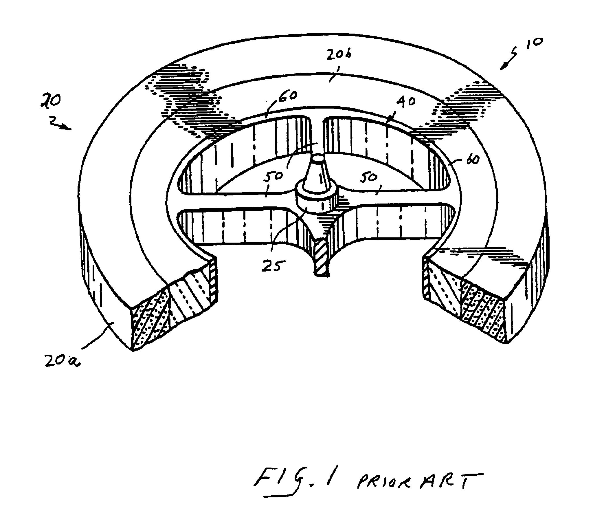
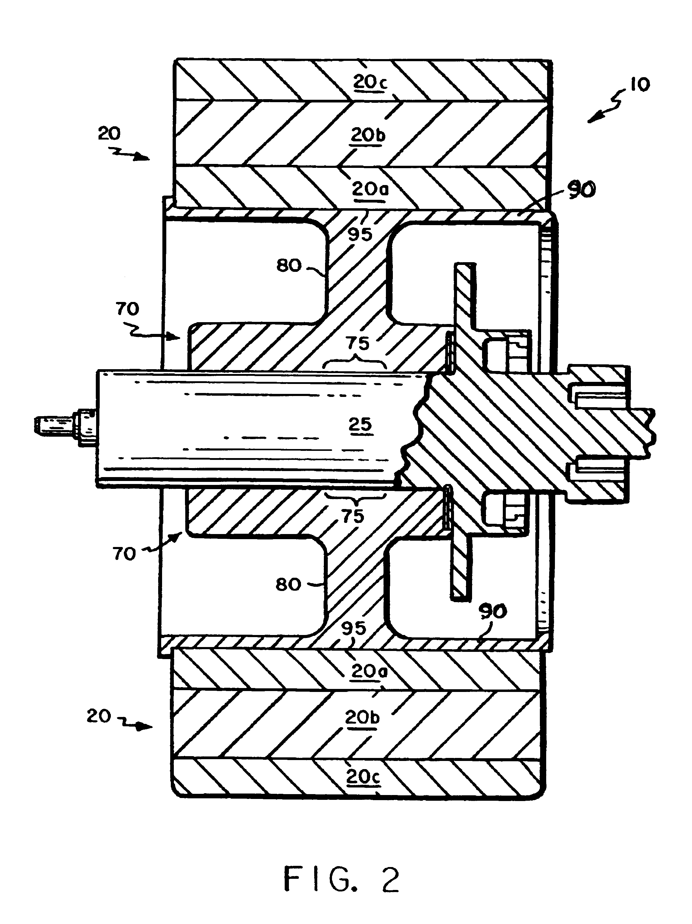
Flywheel-based energy storage devices 10 comprise relatively simple devices for readily storing and recovering energy. See FIGS. 1 through 3. Conceptually, as a flywheel 10 spins in a vacuum, mechanical kinetic energy is stored, e.g., primarily in the outermost portion (the "rim") of the flywheel assembly 10. The amount of energy stored in a flywheel assembly 10 is directly proportional to its mass and to the square of the rotational velocity of the flywheel 10. The rotational velocity of the flywheel 10 is largely responsible for the energy storage capacity due to the effect squaring the velocity has on energy storage. Hence, those of skill in the art are developing flywheels 10 that rotate at ever-increasing velocities.

Thus, those of ordinary skill in the art recognize an effective means to increase a flywheel assembly's 10 energy storage capacity is by maximizing rotational inertia by using high-tensile strength, low-density materials, e.g., composite fiber materials at the outer...


PUM


Abstract

Several embodiments of a stiff, metallic hub for an energy storage devices are disclosed in the present invention. The stiff hub produces a critical velocity that is significantly greater than the design operating speed of the flywheel assembly so that resonant frequency is never reached during normal operation of the energy storage device's flywheel assembly. The stiff hub comprises a central core section that maintains a tight interference fit with the rotating shaft; an outer rim section that maintains a tight interference with the high-strength, low-density composite fiber rim, in which energy primarily is stored; and a web section that is situated therebetween, extending radially from the rotary shaft. At high operating speeds, the outer rim of the hub expands radially commensurate with expansion of the composite fiber rim so that enough of the outer rim remains in tight interference fit with the composite fiber rim to substantially minimize vibrations.

Description

The present invention relates to a metal hub for an energy storage rotor. More precisely, the invention relates to a stiff metal hub for a flywheel that maintains tight interference fit with a radially-deflecting composite rim during high-speed operation by deflecting at the hub outer rim, which minimizes vibrations, and produces a critical velocity substantially higher than the design operating velocity.DESCRIPTION OF THE RELATED ARTEnergy storage rotors, or flywheels, which internally produce and store kinetic energy, have been available as an alternative to batteries and other means of storing energy for about 30 years. Initially, flywheel assemblies were made of metal, e.g., high strength steel. However, flywheels made from composite materials provide superior energy storage capability to steel flywheels as the high-strength, lighter-weight composite flywheels can be rotated at greater speed. Recognizing that energy storage is proportional to the flywheel mass and the square of ...

Claims


Application Information

Patent Timeline
IPC IPC(8): F16F15/315F16F15/30F16F15/305
CPCF16F15/315Y10T74/2119Y10T403/7037Y02E60/16F16C15/00
Inventor BRACKETT, NORMAN C.
Owner BEACON POWER LLC
Why Eureka
Try Eureka