Mosaic-like brick and mosaic-like surfaces made using such bricks

a technology of mosaic-like bricks and mosaic-like surfaces, which is applied in the direction of manufacturing tools, single-unit pavings, and ways, can solve the problems of extreme cost and time-consuming processes, and achieve the effect of enhancing the decorative appearance of patios, and enhancing the mosaic simulation

Inactive Publication Date: 2004-11-23
VOS TERRANCE D
View PDF16 Cites 31 Cited by
  • Summary
  • Abstract
  • Description
  • Claims
  • Application Information

AI Technical Summary

Benefits of technology

Still another object of this invention is to provide a decorative brick which allows rapid creation of mosaic-like patios.
Still another object of the invention is to provide an improved decorative brick and method for making a decorative brick with display-face portions giving the visual impression of each portion representing a separate solid piece as is typically used in formation of mosaic surfaces.
It is highly preferred that a filler be located within the interconnected grooves. In one version of such embodiment, the filler is sand. The sand is preferably loosely located within the grooves. Such a network of grooves forms a mosaic on the display face, and the sand or other filler serves to enhance the mosaic-like appearance of the decorative brick of this invention.
The first decorative bricks and second decorative bricks of such patio are preferably positioned among each other in an edge-adjacent array. Most preferably, the first decorative bricks in the array are oriented in a plurality of different orientations, and the second decorative bricks in the array are oriented in a plurality of different orientations. This greatly enhances the mosaic simulation, because it creates a large number of relationships which tend to "hide" the fact that, at least in some embodiments, all the first decorative bricks have the same patterns of interconnected grooves, and all of the second decorative bricks have the same patterns (but different from the pattern of the first decorative bricks) of interconnected grooves.
The variation and decorative appearance of patios in accordance with this invention can also be enhanced by using decorative bricks of this invention with markedly difference densities of "pieces" on their decorative faces.

Problems solved by technology

Laying horizontal patio surfaces using a great number of somewhat randomly shaped pieces of stone, brick material or the like, in some sort of mosaic pattern or the like, is an extremely expensive and time-consuming process, but the resulting patio surfaces are usually extremely attractive and valuable.

Method used


Image

  • Mosaic-like brick and mosaic-like surfaces made using such bricks
  • Mosaic-like brick and mosaic-like surfaces made using such bricks
  • Mosaic-like brick and mosaic-like surfaces made using such bricks

Examples


Embodiment Construction

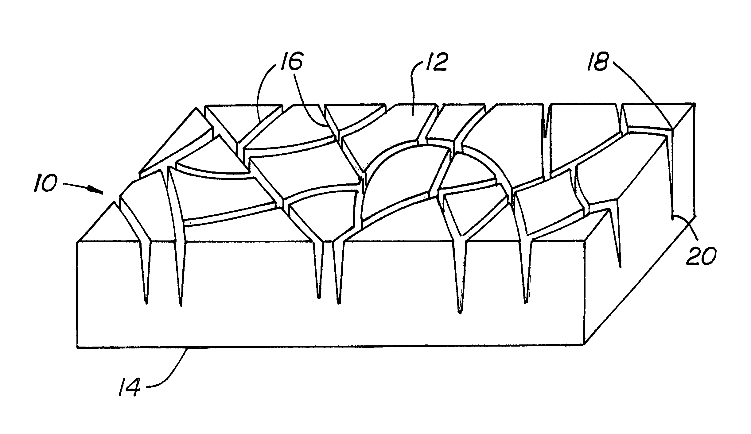
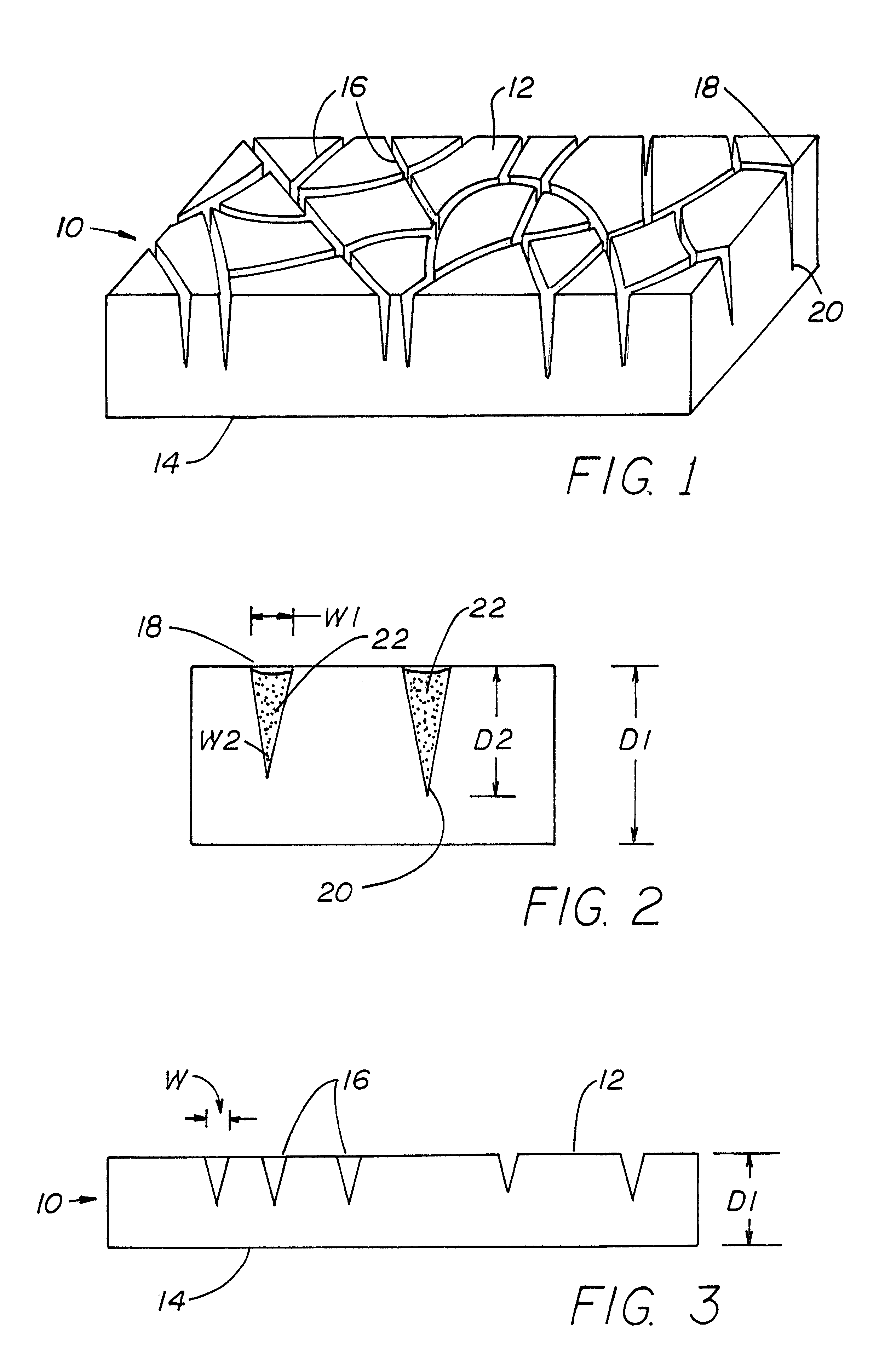
FIGS. 1-3 illustrate the improved brick 10 of this invention in greatest detail. Brick 10 has a display face 12 and a back face 14 that are spaced apart by a first dimension D1. Brick 10 has, formed on display face 12, a network of interconnected grooves 16 having widths W. Grooves 16 extend into brick 10 from display face 12 toward back face 14 to a depth D2 that is more than four times the widths of grooves 16. The interconnected grooves 16 have slightly varying widths.

As illustrated in FIG. 2, grooves 16 each have an elongate open end 18 (defined between a pair of spaced edges) and an elongate closed end 20. The elongate open end 18 has a first width W1 and the elongate closed end 20 has a second width W2. First width W1 is greater than second width W2.

In such an embodiment, first dimension D1 separating display face 12 and back face 14 is between approximately 21 / 2 to 3 inches. In some cases, first dimension D1 may be greater; such thicker brick is often used for driveways and t...


PUM

PropertyMeasurementUnit
depthaaaaaaaaaa
lengthsaaaaaaaaaa
depthsaaaaaaaaaa

Abstract

An improved decorative brick having a display face with a network of deep interconnected grooves to produce a mosaic-like appearance, and patios made with such brick. A manufacturing method for such decorative brick.

Description

This invention is related generally to decorative bricks and brickwork and, more particularly, to bricks used for aesthetic display.Bricks and brickwork, including bricks and brickwork for patios, are a well known art. Indeed, bricks having been made and used since as far back as 1330 B.C. Bricks are one of mankind's oldest known manufactured materials, and have been found in the ruins of ancient civilizations including parts of the Great Wall of China.Bricks are made from a mixture usually comprised of clay and shale that has been ground to a fine consistency. Such a mixture is mixed with water, blended and then fired to approximately 2000.degree. F. During such heating process, the molecular and / or crystalline structure of the clay is changed; the clay is vitrified much like a clay pot that has gone through a firing process. The color of brick is determined by the raw materials it contains, the additives and coatings applied to the surface, and the variance of firing atmosphere kn...

Claims


Application Information

Patent Timeline
Patent Type & Authority Patents(United States)
IPC IPC(8): B28B7/00E01C5/04E04F21/24E04F15/08E04F21/02E04F21/16E04F21/00B44C1/28B44C3/04B44F11/04
CPCB28B7/0064B44C1/28B44C3/046E04F21/24E01C5/04E04F15/08E04F21/16B44F11/04E04F21/04
Inventor VOS, TERRANCE D.
Owner VOS TERRANCE D
Why Eureka
Try Eureka