Conveying apparatus

a technology of conveying equipment and conveyors, which is applied in the direction of conveyor control devices, conveyor parts, roller-ways, etc., can solve the problems of complex and expensive assembly of the conveying equipment, the principle does not apply to the downstream end region of such a transportation line, and it is difficult for this article to make a sharp change in the rotational direction from forward to rearward

Inactive Publication Date: 2004-11-23
ITO DENKI KK
View PDF7 Cites 52 Cited by
  • Summary
  • Abstract
  • Description
  • Claims
  • Application Information

AI Technical Summary

Benefits of technology

Due to elimination of the prior art sensors and relevant devices, the number of constituent parts is reduced in this conveying apparatus, rendering it simple in structure, easy to assemble and maintain, and thus inexpensive to manufacture.
In this way, the presence / absence of article can be detected more precisely.

Problems solved by technology

However, this principle does not apply to the downstream end region of such a transportation line.
Such a considerably large number of constituent parts have rendered complicated the prior art conveying apparatus, consequently and problematically making it intricate and expensive to assemble the apparatus.
In a case wherein any article is moving on and along this apparatus, the article's inertial force being imparted to the motor will be of such an intensity that it is difficult for this article to make a sharp change in rotational direction from forward to rearward.

Method used


Image

  • Conveying apparatus
  • Conveying apparatus
  • Conveying apparatus

Examples


Embodiment Construction

Now, some embodiments of the present invention will be described in detail referring to the drawings.

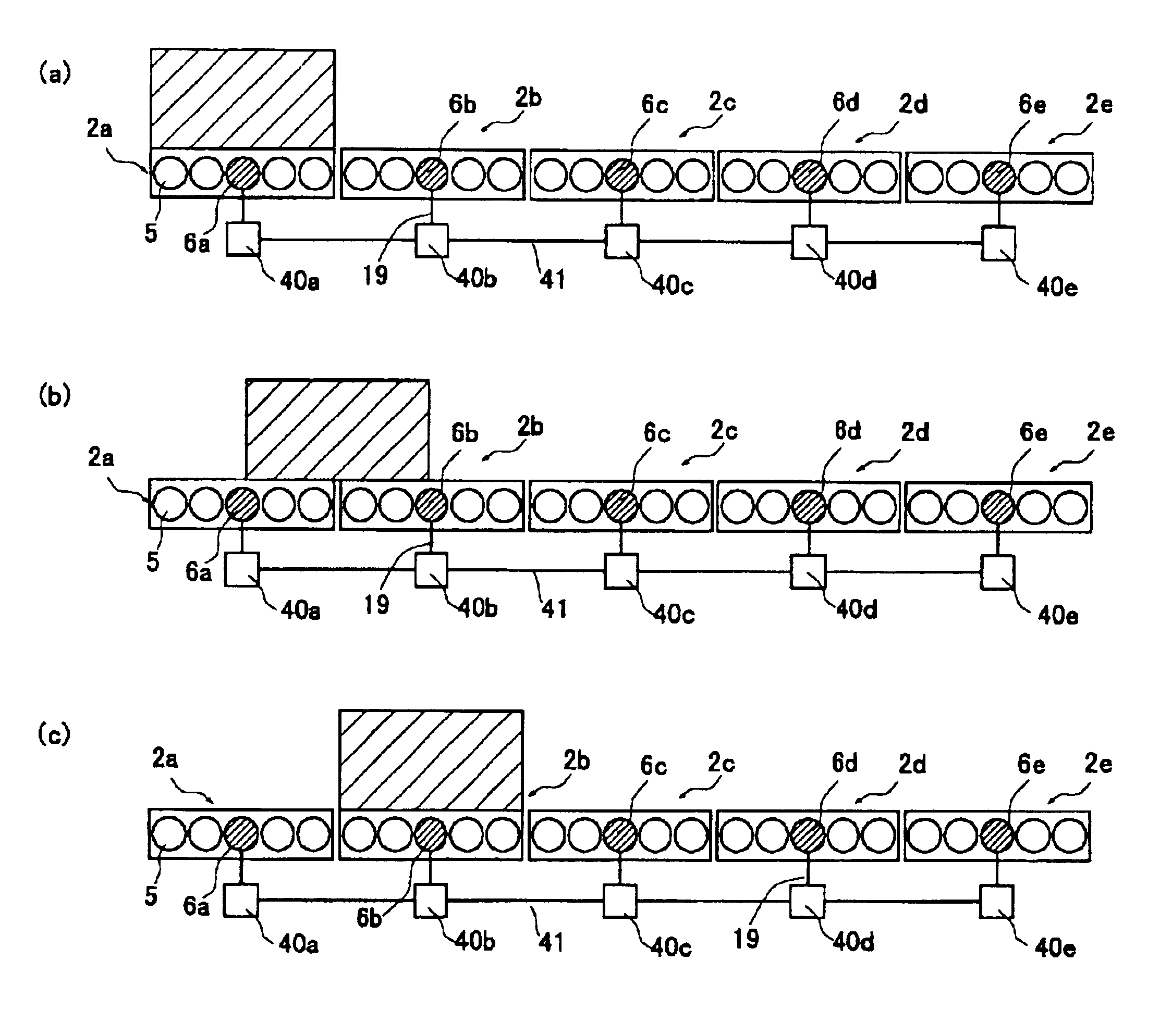
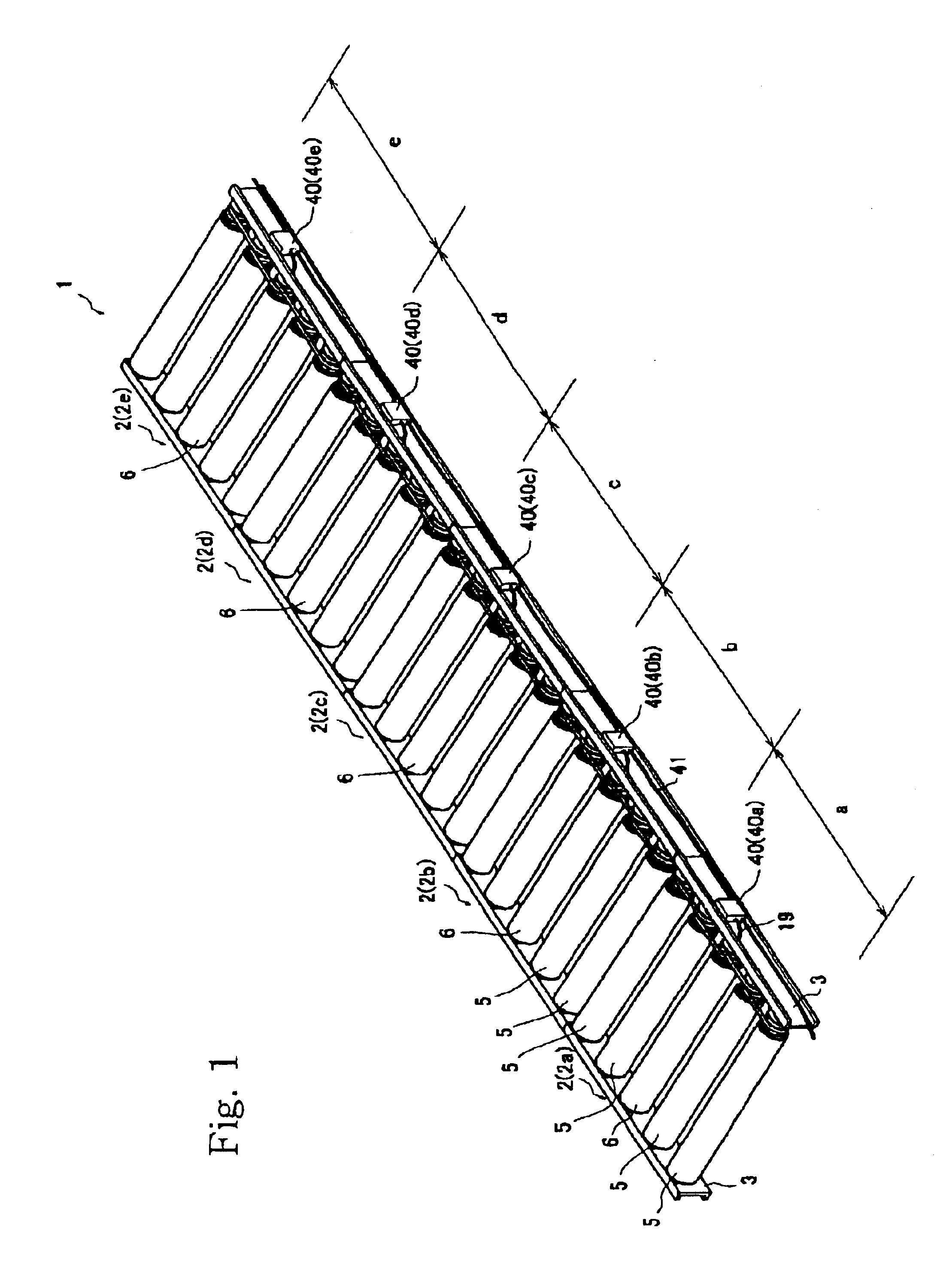
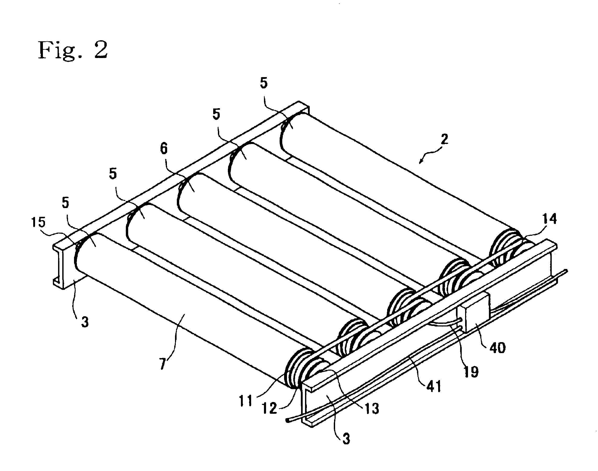
A conveying apparatus 1 consists of 5 (five) modules 2 (viz., 2a, 2b, 2c, 2d and 2e) that are connected one to another in this order along the conveying line, in an example shown in FIG. 1. In other words, such a conveying line is divided into five sequential unit zones `a`, `b`, `c`, `d` and `e` arranged in this order. Each module 2 is composed of 4 (four) free rollers 5 and 1 (one) motorized roller 6 that are supported in parallel by and between frames 3 and 3 extending in parallel with each other. In each module 2 defining one of the unit zones of the conveying line, the motorized roller 6 is disposed at the point midway in this unit zone in a direction of article transportation. Two of the free rollers 5 lie on a forward side of each motorized roller 6, with the other two free rollers lying on a rearward side of this motorized roller, all in parallel with each other.

Each free or ...


PUM


Abstract

A conveying apparatus (1) is composed of several conveying modules (2) each having a controller (40) for control of a motorized roller (6) having a motor (16) incorporated in it. A motor-controlling section (45) installed in the controller (40) operates to sense an article being transported on and along the module (2). An article-state detector (48) included in the motor-controlling section (45) compares the actual number (Pr) of signal pulses indicating the number of rotations of the motor (16) with a standard number (P) of such pulses, when judging whether the article is or is not on the module, without aid of any conventional and discrete prior art sensors.

Description

1. Field of the InventionThe present invention relates to a conveying apparatus composed of a plurality of rollers, and more particularly relates to a conveying apparatus composed of a plurality of rollers and characterized by a controller that controls the operative performance of said conveying apparatus.2. Relevant Prior ArtVarious types of conveying apparatuses have widely been used in industries wherein each apparatus was composed of a plurality of rollers as illustrated in FIG. 13. This conveying apparatus 100 comprises a pair of frames 101 disposed in parallel with each other and supporting between them the rollers 102 and 103. Some of those rollers 102 are free rollers capable of rotating freely relative to their shafts. The other rollers 103 are each a motor-installed roller that has secured therein a motor and a speed reducer, so that this motor actuates each roller 103 to positively rotate about its axis.Such a conveying apparatus 100 comprises also a plurality of sensors...

Claims


Application Information

Patent Timeline
Patent Type & Authority Patents(United States)
IPC IPC(8): B65G47/31B65G39/00B65G43/08B65G43/10B65G39/02
CPCB65G39/02B65G43/08B65G47/31B65G43/10B65G2203/042
Inventor ITOH, KAZUONAGAI, YOSHINORI
Owner ITO DENKI KK
Why Eureka
Try Eureka