Former and process for producing a tissue web

a technology of tissue web and former, which is applied in the direction of papermaking, non-fibrous pulp addition, press section, etc., can solve the problems of loss of quality in the web being produced, runability problems that can also occur in the tissue machine, and counteract the tendency for contamination of the dsp wir

Inactive Publication Date: 2004-11-23
VOITH PATENT GMBH
View PDF22 Cites 71 Cited by
  • Summary
  • Abstract
  • Description
  • Claims
  • Application Information

AI Technical Summary

Benefits of technology

According to one embodiment of the former according to the invention, the vacuum provided in the suction element is adjustable. Thus, a problem-free adjustment of each operational condition (basis weight, porosity of the web, speed) is possible.
According to another embodiment, the forming element is provided with a suction zone in which a corresponding vacuum is preferably adjustable. Using the adjustable vacuum allows for the contact intensity between the tissue web and the inner belt to be modified and / or adjusted. By utilizing an increased vacuum, for instance, the adhesion of the web to the outer belt can be reduced. Moreover, this acts to increase the adhesion between the tissue web and the inner belt, which improves the separation accordingly.
According to another aspect of the invention, the former includes at least one of the two dewatering belts which is embodied as a dewatering belt with zonally variable wire permeability, i.e., a DSP wire and a conditioning device which may be a wire cleaning device. The conditioning device being assigned to such a dewatering wire. This design counteracts the tendency for contamination of the DSP wire, which is based on fibers invading the volume of the wire and sticking due to its variable permeability. Moreover, this design reduces corresponding contamination of the wire, which affects the performance of the wire, and thus the quality of the tissue web. Thus, the disadvantages which occur because of contamination are avoided by the conditioning device and / or wire cleaning device according to the invention. According to one embodiment, the conditioning device may have the form of, for instance, spray pipes having jets provided over the width of the machine. A traversing conditioning device may also be used, e.g., a "Duocleaner" (cf. EP-O 731 212 A) made by the company Voith Sulzer and having both rotating high pressurized jets and integrated suctioning. A "Jet Cleaner" made by the company Voith Sulzer, for instance, may also be used. U.S. Pat. No. 5,783,044 illustrates a "Duocleaner" which may be used; this document being expressly incorporated by reference in its entirety.
The conditioning device is preferably embodied such that it affects the dewatering belt at least essentially over its entire width. Moreover, a cleaning device operating accordingly over the entire width (e.g., spray pipes with jets positioned over the width of the machine, Jet Cleaner, cleaning roll, etc) can be used in combination with a traversing locally intense operating cleaning device (e.g., Duocleaner, high pressure jet). By combining such cleaning elements, wire wear can be minimized at the same time that sufficiently good cleaning effects are maintained.
This design acts to counteract the tendency for contamination of the corresponding DSP wire.

Problems solved by technology

However, this separation process causes problems when the outer belt is very rough and / or very open.
Such problems can even occur when the wire is one with a zonally variable wire permeability, i.e., a so-called DSP wire.
This is disadvantageous since the tissue web may undesirably tend to travel along with the outer wire.
Furthermore, it is also disadvantageous because the fibers, which are interlocked with the outer wire, are not completely removed together with the tissue web from the rough open outer wire during the separation process, but instead partially remain in the outer wire, i.e., undesirably stuck to the outer wire.
During operation, this incomplete separation problem between the fibers and the outer wire leads to an increasing contamination of the outer wire, and thus to a loss of quality in the web being produced.
Runability problems can also occur in the tissue machine as a result or incomplete separation.
This design counteracts the tendency for contamination of the DSP wire, which is based on fibers invading the volume of the wire and sticking due to its variable permeability.
Moreover, this design reduces corresponding contamination of the wire, which affects the performance of the wire, and thus the quality of the tissue web.

Method used


Image

  • Former and process for producing a tissue web
  • Former and process for producing a tissue web
  • Former and process for producing a tissue web

Examples


Embodiment Construction

The particulars shown herein are by way of example and for purposes of illustrative discussion of the embodiments of the present invention only and are presented in the cause of providing what is believed to be the most useful and readily understood description of the principles and conceptual aspects of the present invention. In this regard, no attempt is made to show structural details of the present invention in more detail than is necessary for the fundamental understanding of the present invention, the description taken with the drawings making apparent to those skilled in the art how the several forms of the present invention may be embodied in practice.

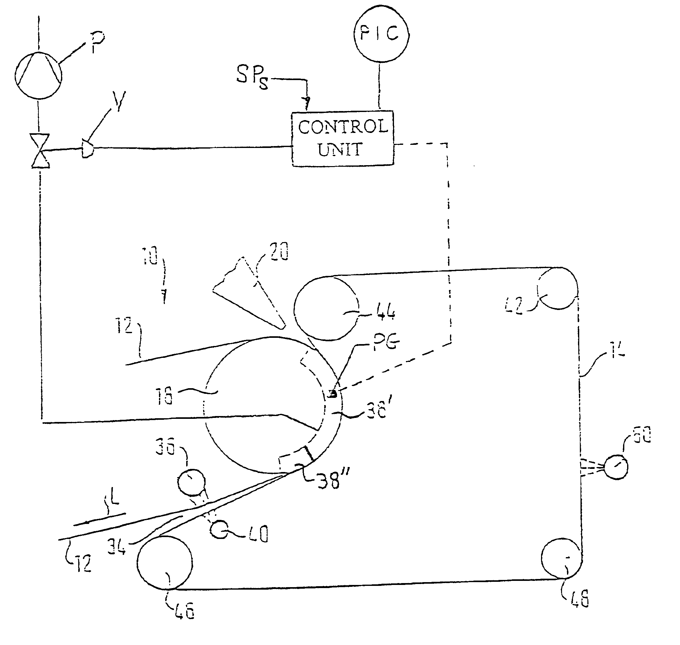
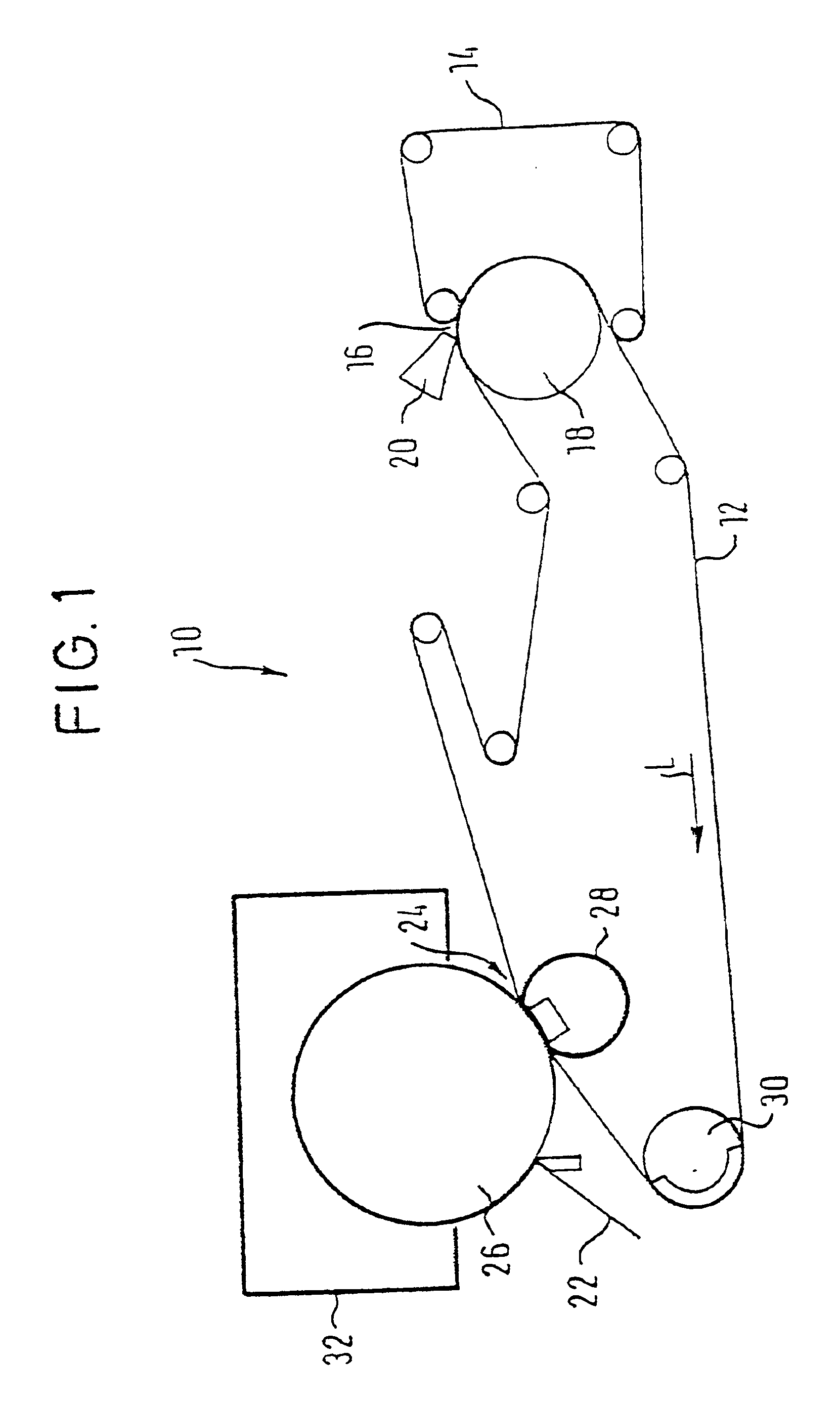
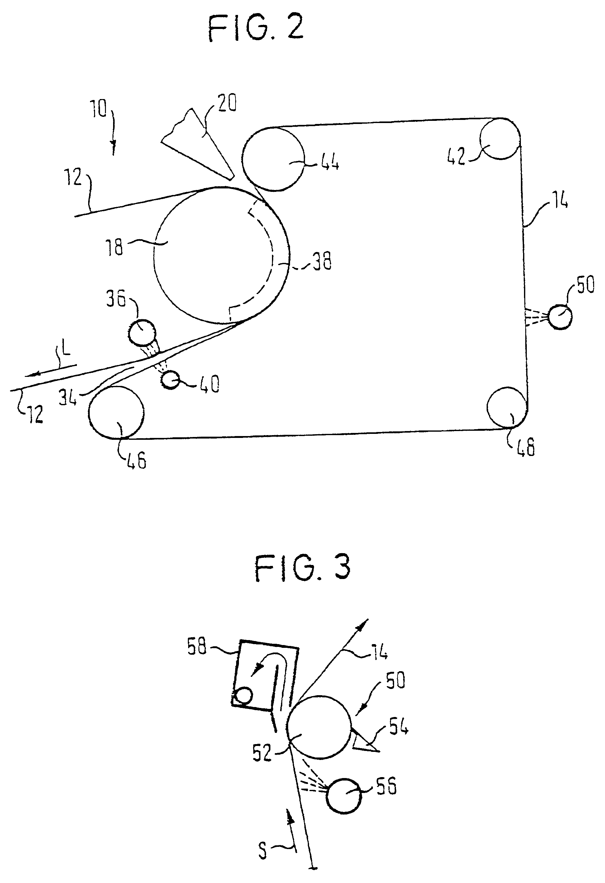
FIG. 1 shows in schematic representation a crescent former 10 of a machine for producing a tissue web 22. Two circulating continuous dewatering belts 12 and 14 are provided and arranged to converge so as to form a stock inlet nip 16. Belts 12 and 14 are subsequently guided over a forming element which may have the form of a for...


PUM

PropertyMeasurementUnit
permeabilityaaaaaaaaaa
areaaaaaaaaaaa
suctionaaaaaaaaaa

Abstract

A former for producing a tissue web and a process of making a tissue web using the former. The former includes a forming element, an inner dewatering belt, and an outer dewatering belt. The inner and outer belts converge to form a stock inlet nip. The inner and outer belts are guided over the forming element and thereafter separating from one another in the area of a separation point. At least one suction element is positioned adjacent the inner belt on a side which is opposite the outer belt. Alternatively, a conditioning device is positioned adjacent the outer belt. The process includes forming the tissue web in the area of the forming element, guiding the inner and outer belts around the forming element, and separating the inner and outer belts in the area of the separation point. Alternatively, the process includes conditioning the outer belt.

Description

The present application claims priority under 35 U.S.C. .sctn.119 of German Patent Application No. 100 03 685.6, filed on Jan. 28, 2000, the disclosure of which is expressly incorporated by reference herein in its entirety.1. Field of the InventionThe invention relates to a former of a machine for producing a tissue web containing two circulating continuous dewatering belts that converge to form a stock inlet nip and which are guided subsequently over a forming element such as, e.g., a forming roll. The invention also relates to a process of making a tissue web using such a former.2. Discussion of Background InformationDouble wire formers and crescent formers are typically used for the production of tissues or tissue webs. In this way, a fibrous suspension is introduced between two dewatering belts which are guided over at least a part of the circumference of a forming roll. In the case of double wire formers, the two dewatering belts are embodied as dewatering wires. In the case of...

Claims


Application Information

Patent Timeline
Patent Type & Authority Patents(United States)
IPC IPC(8): D21F11/14D21F1/32D21F11/00D21F9/00
CPCD21F1/32D21F11/14D21F11/006D21F9/003
Inventor SCHERB, THOMAS THOROESCHMIDT-HEBBEL, HARALD
Owner VOITH PATENT GMBH
Why Eureka
Try Eureka